Power tool

A technology of power tools and drive shafts, applied in the direction of grinding workpiece supports, etc., can solve the problems of time-consuming, inconvenient, laborious operation, etc., and achieve reliable and firm clamping effect

Active Publication Date: 2012-11-21
NANJING CHERVON IND
View PDF8 Cites 11 Cited by
  • Summary
  • Abstract
  • Description
  • Claims
  • Application Information

AI Technical Summary

Problems solved by technology

[0004] The above-mentioned power tool in the prior art also has a defect that the working element clamped on it cannot be adjusted at multiple angles, because the working element is either in the state of being clamped and performing an operation through the clamping device, o

Method used


Image

  • Power tool
  • Power tool
  • Power tool

Examples


Embodiment Construction

[0035] The specific implementation manners of the present invention will be further described in detail below in conjunction with the accompanying drawings.

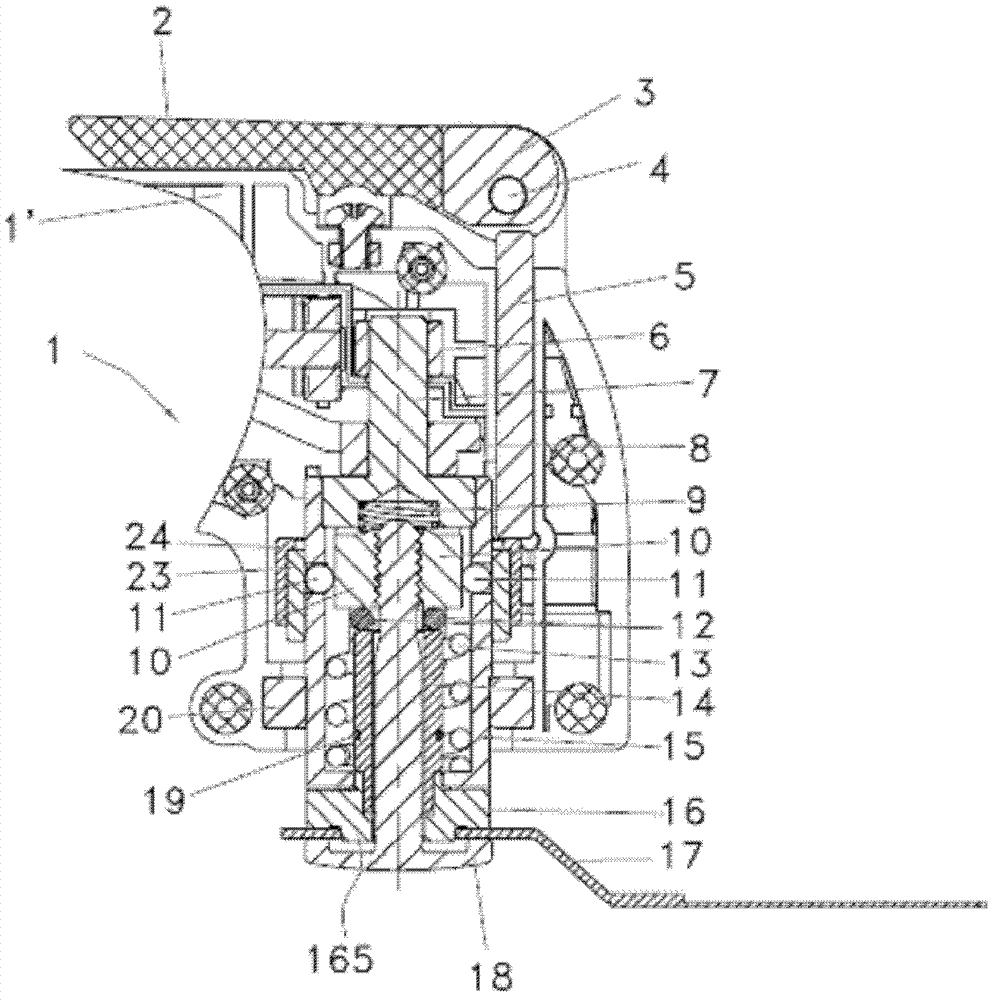
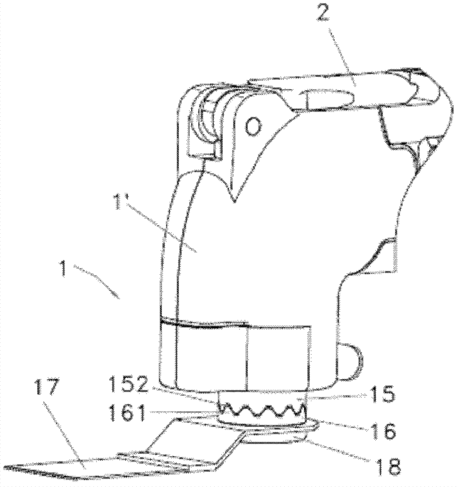
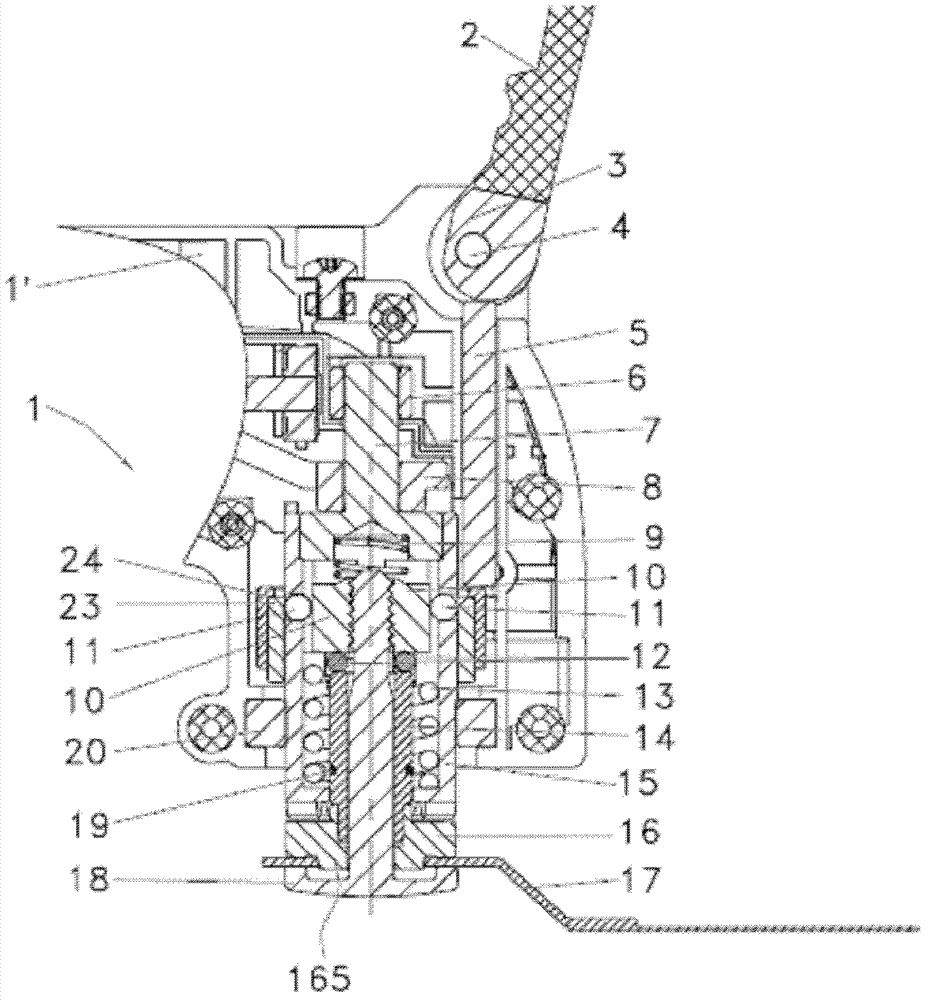
[0036] like Figure 1a to Figure 4c and Figure 7 As shown, the present invention is preferably described as a power tool 1 that drives the working element 17 in a vibrating manner. The driving in a vibrating manner can be broadly understood as the multifunctional tool on the existing market drives its working element to go back and forth around its power output shaft. Rotation or reciprocating motion combined with compound motion such as reciprocating movement, the working element can be broadly understood as a saw blade that can be used for sawing, a grinding wheel that can be used for grinding, etc. In this embodiment, the working element 17 is a saw blade. For saw blades used for cutting, the power drive shaft of the power tool 1 is supported by bearings 6 and 20, and under the action of the vibrating support 8, it ...


PUM


Abstract

The invention provides a power tool which comprises a driving shaft, wherein the driving shaft is provided with a longitudinal axis and drives a work element in a way of vibration through a torque drive structure; the work element is provided with s first working position and at least one second working position which vibrate around the longitudinal axis, and the second working position is provided with a transposition angle relative to the first working position; the work element is clamped on an upper clamping mechanism of the power tool, wherein the work element and the torque drive structure can be trans-positioned from the first working position to the second working position in a way of non-disconnection. Compared with the existing power tool in transposition adjustment of the work element, the work element does not need to be taken down so as to achieve angle adjustment of the work element, so that the power tool is time saving and labor saving.

Description

technical field [0001] The present invention relates to a power tool comprising an output shaft for driving the tool and a fastener for clamping a working element to the end of the output shaft, and a fastener for making the fastener A moving device that moves between a released position and a clamped position, in which the fastener can be removed from the output shaft by disengaging from the moving device, whereas in the clamped position, the fastener is locked by the moving device The joint and the elastic element work together to support the end of the output shaft so that the working element is firmly clamped. Background technique [0002] Known from US6569001B2 is a power tool with a quick clamping device, the hand tool is an angle grinder, the angle grinder is equipped with a hollow output shaft, and the hollow shaft is equipped with a Clamping device movable between a clamped position and a released position, the clamping device comprises a clamping flange with a thr...

Claims


Application Information

Patent Timeline
IPC IPC(8): B24B41/06
Inventor 周红陶
Owner NANJING CHERVON IND
Why Eureka
Try Eureka