

Energy dissipater in wading engineering
An energy dissipator and engineering technology, applied in water conservancy engineering, marine engineering, coastline protection, etc., can solve problems such as affecting the safe operation of structures, losing energy dissipation effect, restricting application, etc., to avoid water hammer, reduce impact damage, avoid effect of deposition
- Summary
- Abstract
- Description
- Claims
- Application Information
AI Technical Summary
Problems solved by technology
Method used
Image

Examples
Embodiment 1
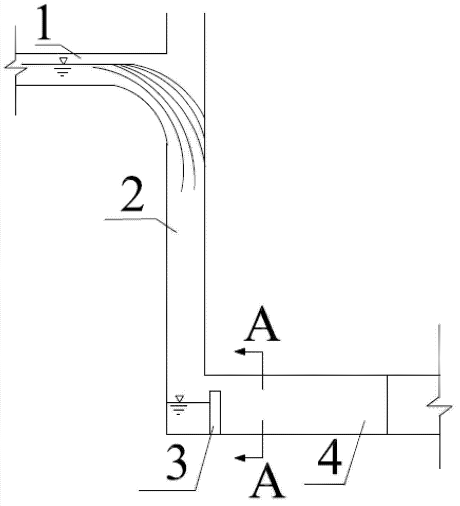
[0024] Such as figure 1 As shown, a specific embodiment of the present invention is a kind of wading engineering energy dissipator, comprising a water pipeline 1 used as an upstream water delivery structure, a shaft 2 used as a drop structure, and a water retaining wall used as a flow control structure 3 and a drainage pipeline 4 used as a downstream water delivery structure; the water delivery pipeline 1 is connected to the drainage pipeline 4 through a vertical shaft 2; The downstream end is provided with a retaining wall 3 .
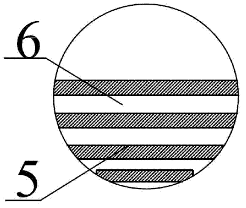
[0025] Such as figure 2 As shown, the water retaining wall 3 is composed of a plurality of slats arranged parallel to each other on the same plane. The slats 5 are erected horizontally in the drainage pipe 4, and water holes 6 are arranged between adjacent slats 5 to retain water. The space formed between the wall 3 and the end (equivalent to the stilling well) corresponds to the position below the connection between the vertical shaft 2 and the dr...
Embodiment 2
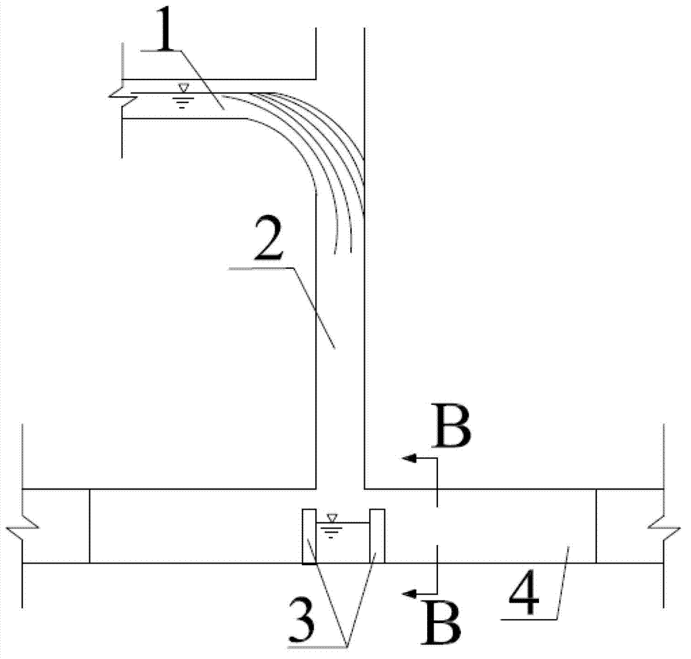
[0031] Such as image 3 As shown, another specific embodiment of a kind of wading engineering energy dissipation device of the present invention is basically the same as Embodiment 1, the difference is that the vertical shaft 2 is connected to the middle section of the drainage pipe 4, and the retaining wall has two sides , opposite to each other and arranged on the bottom of the drainage pipe, the space formed between the water retaining wall 3 and the drainage pipe 4 (equivalent to the stilling well) corresponds to the position below the connection between the vertical shaft 2 and the drainage pipe 4 .
[0032] Such as Figure 4 As shown, the slats of the retaining wall 3 are vertically arranged.
[0033] As other specific embodiments of the present invention, the upstream water conveyance structure, falling water structure, flow control structure and downstream water conveyance structure can all be adapted to other structures according to construction needs, such as direct...
PUM
 Abstract
Description
Claims
Application Information