Novel hydraulic gear-shifting pressure regulating valve

A pressure regulation and hydraulic technology, applied to components with teeth, belts/chains/gears, mechanical equipment, etc., can solve the problems of increased shift time, prolonged oil filling process of shift clutches, etc., to shorten shift time Effect

Inactive Publication Date: 2012-11-21
SICHUAN UNIV
View PDF7 Cites 5 Cited by
  • Summary
  • Abstract
  • Description
  • Claims
  • Application Information

AI Technical Summary

Problems solved by technology

With the hydraulic shift pressure regulating valve of this structure, the shift clutch oil cylinder is quickly filled with oil at the initial stage of shifting. When the hydraulic oil overcomes the pre-pressure of the shift clutch release spring and eliminates the gap between the friction plates, the pressure control valve spool The oil pressure at the oil outlet rises and acts directly on the left end of th

Method used


Image

  • Novel hydraulic gear-shifting pressure regulating valve
  • Novel hydraulic gear-shifting pressure regulating valve
  • Novel hydraulic gear-shifting pressure regulating valve

Examples


Example Embodiment

[0020] Example 1:

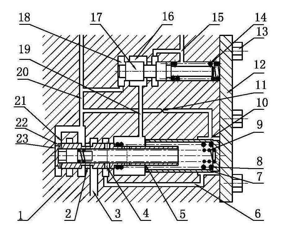
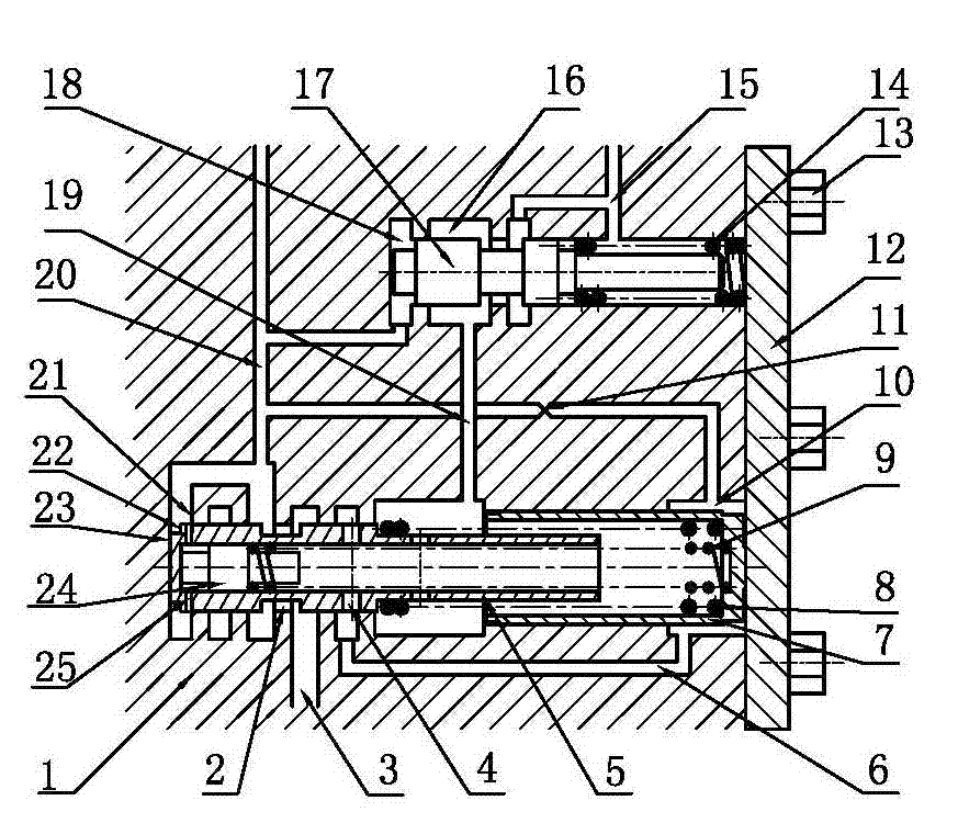
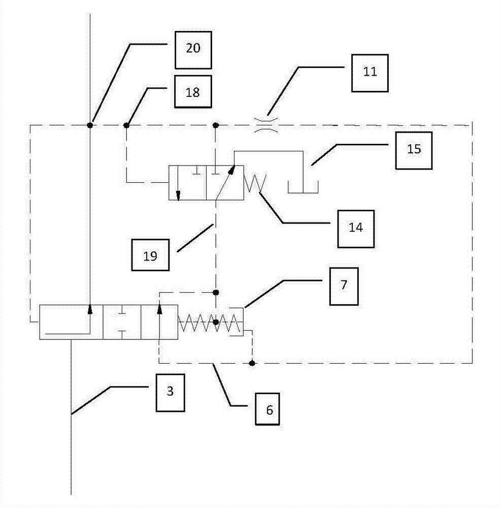
[0021] see image 3 , a new type of hydraulic shift pressure regulating valve, mainly including body, pressure control valve spool, accumulator plunger, accumulator main spring, accumulator auxiliary spring, orifice, pressure setting valve spring, pressure Set valve spool, quick oil filling spool, quick oil filling small hole. The pressure control valve spool is arranged in the body of the hydraulic shift pressure regulating valve. The pressure control valve spool is provided with a quick oil filling spool. The left end of the secondary spring of the accumulator interacts with the right end of the quick oil filling spool to store the oil. The right end of the accumulator secondary spring interacts with the accumulator plunger, the left end of the accumulator main spring interacts with the pressure control valve spool, the right end of the accumulator main spring interacts with the accumulator plunger, and the pressure control valve Part of the inner surfa...


PUM

PropertyMeasurementUnit
Lengthaaaaaaaaaa

Abstract

A novel hydraulic gear-shifting pressure regulating valve mainly comprises a body, a valve core of a pressure control valve, a plunger of an energy accumulator, a main spring of the energy accumulator, an auxiliary spring of the energy accumulator, a throttling hole, a spring of a pressure setting valve, a valve core of the pressure setting valve, a fast oil charge valve core, and a fast oil charge hole. The valve core of the pressure control valve is arranged in the body of the hydraulic gear-shifting pressure regulating valve, the fast oil charge valve core is arranged inside the valve core of the pressure control valve, the left end of the auxiliary spring of the energy accumulator and the right end of the fast oil charge valve core are acted mutually, the right end of the auxiliary spring of the energy accumulator and the plunger of the energy accumulator are acted mutually, the left end of the main spring of the energy accumulator and the valve core of the pressure control valve are acted mutually, the right end of the main spring of the energy accumulator and the plunger of the energy accumulator are acted mutually, and an oil seal cavity is formed by partial inner surface of the valve core of the pressure control valve and the fast oil charge valve core, and is communicated with the space outside the valve core of the pressure control valve through the fast oil charge hole on the valve core of the pressure control valve. At the gear-shifting clutch fast oil charge stage, the novel hydraulic gear-shifting pressure regulating valve can always keep the larger opening degree of an adjustable valve port of the valve core of the pressure control valve, enable hydraulic oil to be charged into a gear-shifting clutch oil cylinder at a speed higher than that of the traditional hydraulic gear-shifting pressure regulating valve, thereby shortening the gear-shifting time.

Description

technical field [0001] The invention relates to a novel hydraulic shifting pressure regulating valve, in particular to a hydraulic shifting pressure regulating valve which can effectively shorten the shifting time of large construction machinery and heavy trucks. Background technique [0002] With the continuous development and maturity of construction machinery and heavy trucks in my country, people have higher and higher requirements for shift quality, and the application of power shift gearboxes in domestic construction machinery and heavy trucks is becoming more and more popular. The important characteristics of the power shift transmission are the smoothness and quickness of the shift, which is mainly guaranteed by the combination of the hydraulic shift pressure regulating valve to control the shift clutch. [0003] The clutch hydraulic oil cylinder needs to go through three stages in the whole combination process of the shifting clutch: the rapid oil filling stage, the...

Claims


Application Information

Patent Timeline
IPC IPC(8): F16H61/28
Inventor 韩嘉骅
Owner SICHUAN UNIV
Why Eureka
Try Eureka