
Stereoscopic image display system

A display system and stereoscopic image technology, applied in stereoscopic systems, image communications, static indicators, etc., can solve the problems of increasing the vertical viewing angle of the stereoscopic image display system, image information crosstalk, etc., and achieve the goal of solving image information crosstalk and increasing the vertical viewing angle Effect

Inactive Publication Date: 2012-11-21
TCL CHINA STAR OPTOELECTRONICS TECH CO LTD
View PDF2 Cites 1 Cited by
  • Summary
  • Abstract
  • Description
  • Claims
  • Application Information

AI Technical Summary

Problems solved by technology

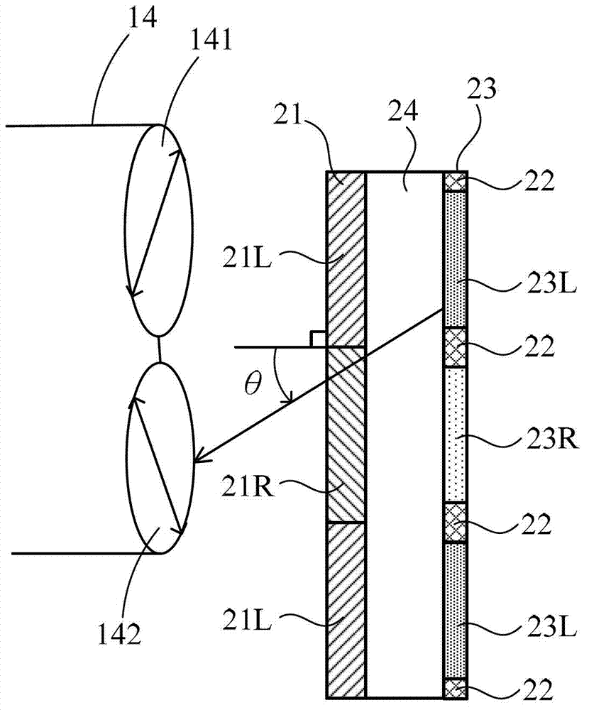
[0005] In view of this, the purpose of the present invention is to provide a stereoscopic image display system, through the corresponding configuration of the frame rate of the liquid crystal display panel and the black line of the pixel, the vertical viewing angle of the stereoscopic image display system can be increased, and the image information crosstalk can be solved. (crosstalk) question

Method used


Image

  • Stereoscopic image display system
  • Stereoscopic image display system
  • Stereoscopic image display system

Examples


Embodiment Construction

[0028] The following descriptions of the various embodiments refer to the accompanying drawings to illustrate specific embodiments in which the present invention can be practiced. The directional terms mentioned in the present invention, such as "up", "down", "front", "back", "left", "right", "top", "bottom", "horizontal", "vertical", etc. , are for orientation only with reference to the attached drawings. Therefore, the directional terms used are used to illustrate and understand the present invention, but not to limit the present invention.

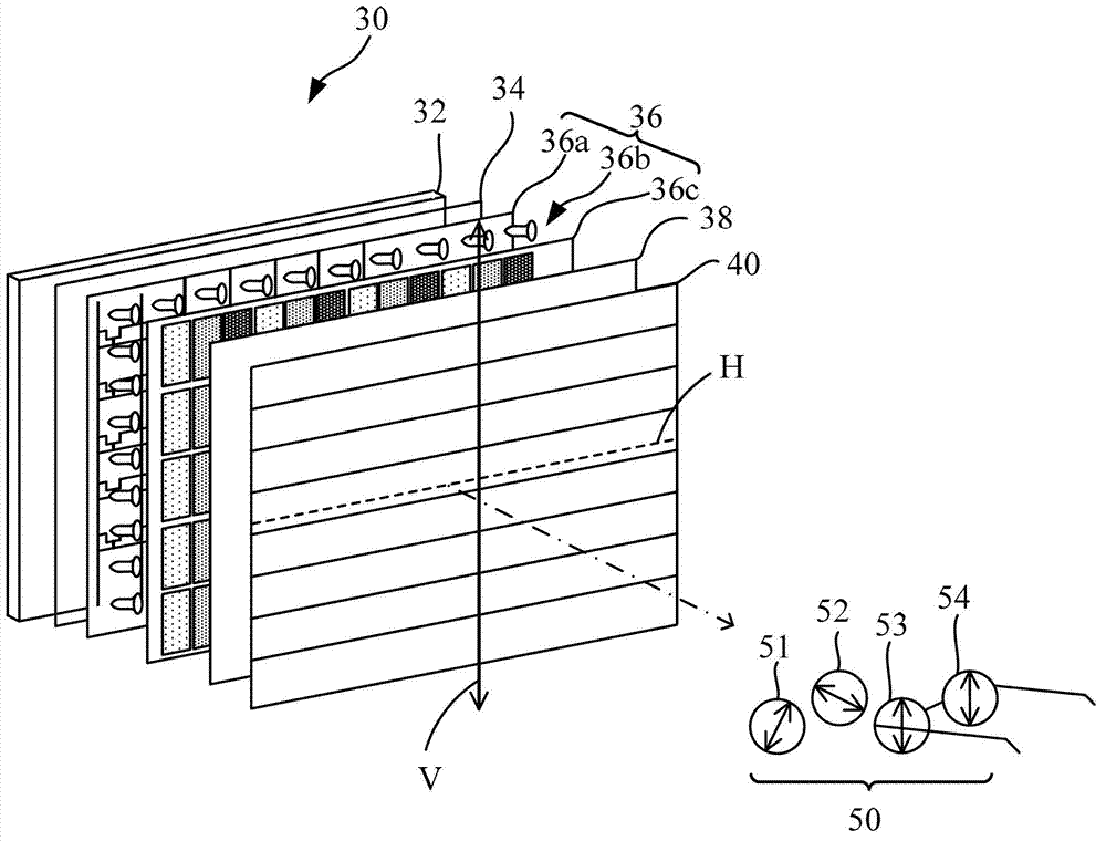
[0029] image 3 It is a schematic diagram of the stereoscopic image display system 30 and the polarized glasses 50 used in conjunction with it in the embodiment of the present invention. Such as image 3 As shown, the stereoscopic image display system 30 includes a backlight plate 32 , a first polarizer 34 , a liquid crystal display panel 36 , a second polarizer 38 and a phase retardation film 40 . The backlight panel 32 is used to ...


PUM


Abstract

The invention relates to a stereoscopic image display system, which is characterized in that a liquid crystal display panel comprises a plurality of first pixel rows and a plurality of second pixel rows, wherein within a frame period, first pixel rows input corresponding first gray scale voltage to display a corresponding first image, the second pixel rows input a first black image voltage to display a first black image; and within the next frame period, the second pixel rows input corresponding second gray voltage to display a corresponding second image and the first pixel rows input second black image voltage to display a second black image. A phase retardation film comprises first phase retardation areas corresponding to the first pixel rows and second phase retardation areas corresponding to the second pixel rows. Through corresponding configuration of frame periods and inserting black lines of pixels, the problem of image information crosstalk is solved.

Description

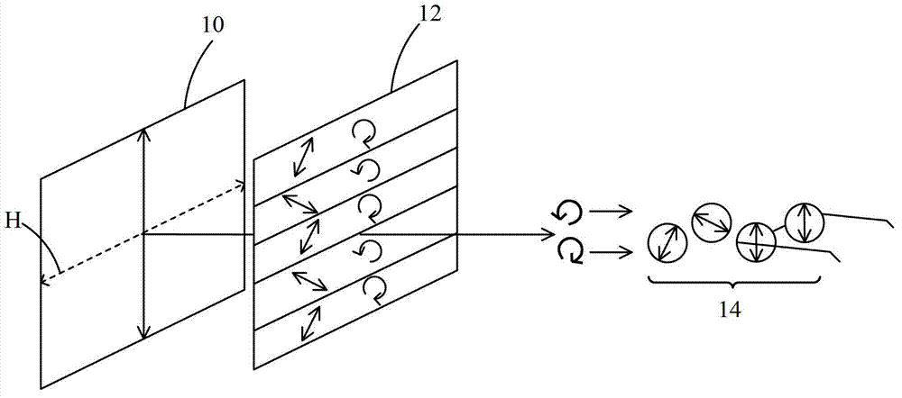
【Technical field】 [0001] The invention relates to a stereoscopic image display technology, and in particular to a stereoscopic image display system. 【Background technique】 [0002] figure 1 A schematic diagram illustrating the working principle of an existing stereoscopic display is shown. Existing 3D displays use a pattern retarder technology and cooperate with polarized glasses to present 3D images. Such as figure 1 As shown, a linear polarizer 10 is arranged on the display panel (not shown) side of the display, and a λ / 4 array wave plate 12 is arranged on the color filter substrate (not shown) side. The light emitted from the backlight module (not shown) of the display will be polarized to form linearly polarized light after passing through the linear polarizer 10 . The optical axis of the linear polarizer 10 forms an included angle of 90° with the horizontal direction H, so only light with a vertical polarization direction can pass through the linear polarizer 10, th...

Claims


Application Information

Patent Timeline
IPC IPC(8): G02F1/13363G02F1/1335G02B27/26H04N13/04G02B30/25
CPCG02B27/26G02F2203/30H04N13/00G02B27/2214G09G3/003H04N13/0434G09G3/36G02F2001/133638G02F1/133G09G3/3607G09G2320/0209G02B30/25G02F1/133638H04N13/337G09G2310/027
Inventor 李佳育
Owner TCL CHINA STAR OPTOELECTRONICS TECH CO LTD
Learn More