Method capable of reducing torque tracking error of switched reluctance motor
A switched reluctance motor, tracking error technology, applied in torque ripple control and other directions, can solve the problem of no active control, and achieve the effects of convenient operation, reducing torque ripple and noise, and reducing torque tracking error
- Summary
- Abstract
- Description
- Claims
- Application Information
AI Technical Summary
Problems solved by technology
Method used
Image
Examples
Embodiment 1
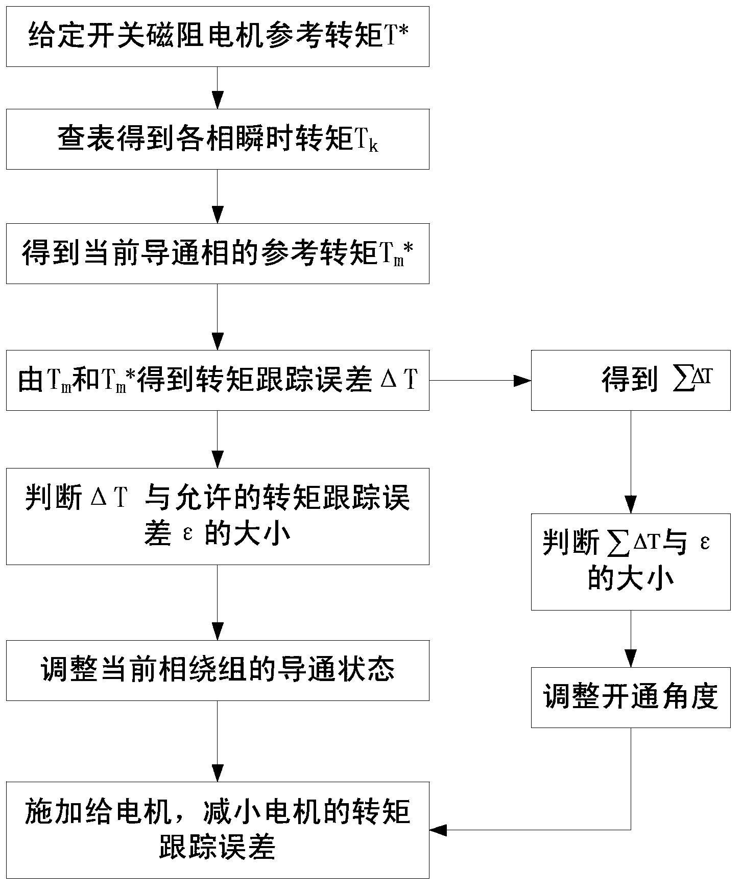
[0047] Embodiment 1: In this embodiment, a switched reluctance motor with a three-phase 6 / 4 structure is taken as an example, as figure 1 shown, including the following steps:
[0048] Step 1: Given the reference torque T of the switched reluctance motor * ;
[0049] When the switched reluctance motor is running electrically, the reference torque T * is positive; when the switched reluctance motor decelerates or brakes, the reference torque T * is negative;
[0050] Step 2: According to the "angle-current-torque" data sheet of the switched reluctance motor, obtain the current i of the stator winding of the switched reluctance motor at different rotor angles θ k The corresponding instantaneous torque T k , k=0, 1, 2...n, k is any phase of the motor, n is the total number of phases of the motor, n=3 in this embodiment;
[0051]The "angle-current-torque" data sheet of the switched reluctance motor is based on the rotor angle θ collected by the position sensor and the curren...
Embodiment 2
[0072] Embodiment 2: This embodiment takes a switched reluctance motor with a four-phase 8 / 6 structure as an example, and the steps are as follows figure 1 As shown, the difference from Embodiment 1 is:
[0073] 1. In this embodiment, n=4;
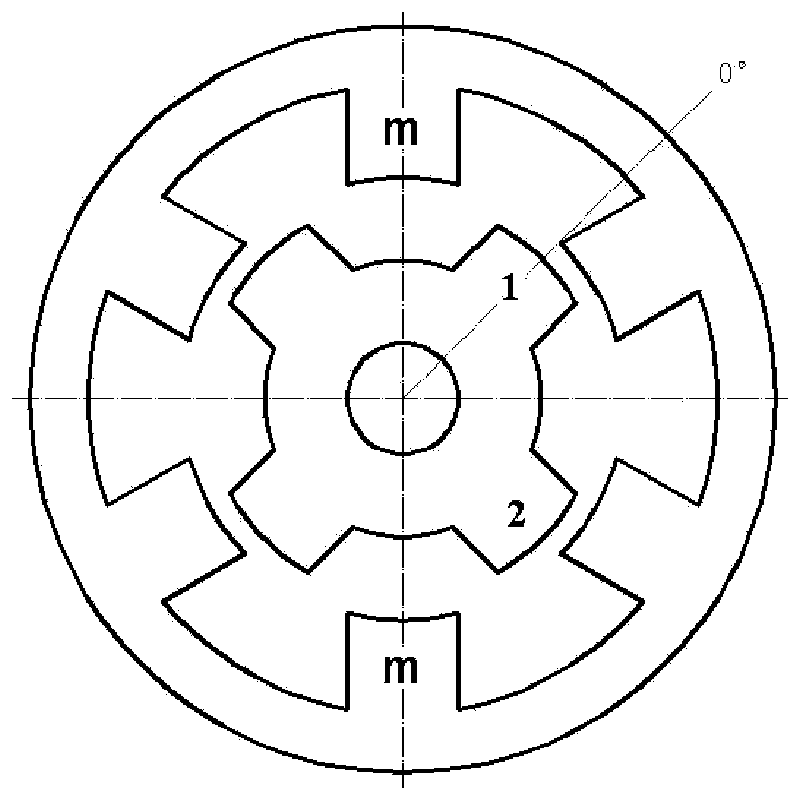
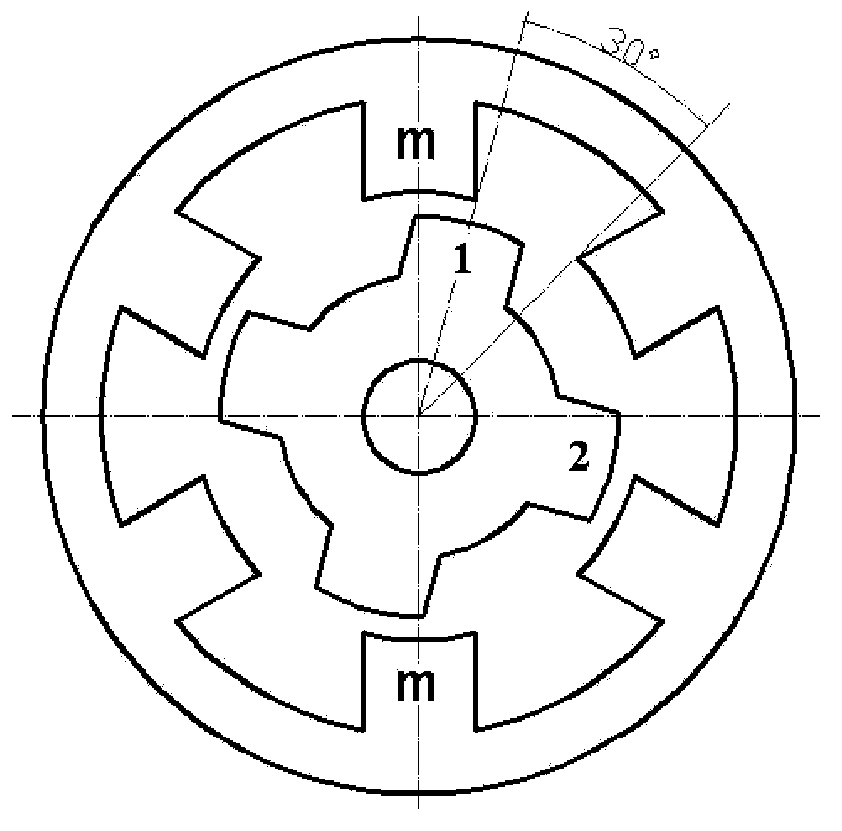
[0074] 2. The phase maximum inductance position of the switched reluctance motor in this embodiment is Figure 9 When the salient poles of the stator and rotor are shown relative to each other, the position of the minimum inductance of the phase is Figure 7 or Figure 11 The positions where the salient poles of the stator are facing the centers of two adjacent rotors are shown.
[0075] 3. In this embodiment, the cut-off angle of the switched reluctance motor is fixed at Figure 8 The 20° position prior to the maximum inductance position shown is not adjusted.
[0076] 4. In this embodiment, when the switched reluctance motor decelerates or brakes, the m phase is turned on after the maximum inductance position is 30°; At the turn-on...
PUM
 Abstract
Description
Claims
Application Information
 - R&D
- Intellectual Property
- Life Sciences
- Materials
- Tech Scout
- Unparalleled Data Quality
- Higher Quality Content
- 60% Fewer Hallucinations
Browse by: Latest US Patents, China's latest patents, Technical Efficacy Thesaurus, Application Domain, Technology Topic, Popular Technical Reports.
© 2025 PatSnap. All rights reserved.Legal|Privacy policy|Modern Slavery Act Transparency Statement|Sitemap|About US| Contact US: help@patsnap.com


