Method capable of reducing torque tracking error of switched reluctance motor

A switched reluctance motor, tracking error technology, applied in torque ripple control and other directions, can solve the problem of no active control, and achieve the effects of convenient operation, reduced torque ripple and noise, and fast calculation speed

Active Publication Date: 2012-11-21
HEFEI UNIV OF TECH
View PDF3 Cites 17 Cited by
  • Summary
  • Abstract
  • Description
  • Claims
  • Application Information

AI Technical Summary

Problems solved by technology

[0004] At present, various control methods do not directly control the torque tracking error of the motor to limit the tracking error.

Method used


Image

  • Method capable of reducing torque tracking error of switched reluctance motor
  • Method capable of reducing torque tracking error of switched reluctance motor
  • Method capable of reducing torque tracking error of switched reluctance motor

Examples


Embodiment 1

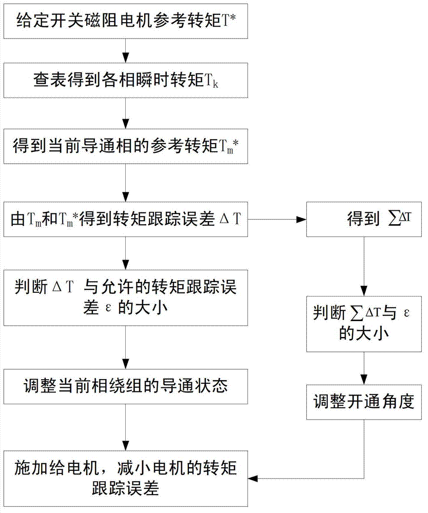
[0047] Embodiment 1: In this embodiment, a switched reluctance motor with a three-phase 6 / 4 structure is taken as an example, as figure 1 shown, including the following steps:

[0048] Step 1: Given the reference torque T of the switched reluctance motor * ;

[0049] When the switched reluctance motor is running electrically, the reference torque T * is positive; when the switched reluctance motor decelerates or brakes, the reference torque T * is negative;

[0050] Step 2: According to the "angle-current-torque" data sheet of the switched reluctance motor, obtain the current i of the stator winding of the switched reluctance motor at different rotor angles θ k The corresponding instantaneous torque T k , k=0, 1, 2...n, k is any phase of the motor, n is the total number of phases of the motor, n=3 in this embodiment;

[0051] The "angle-current-torque" data sheet of the switched reluctance motor is based on the rotor angle θ collected by the position sensor and the current...

Embodiment 2

[0072] Embodiment 2: This embodiment takes a switched reluctance motor with a four-phase 8 / 6 structure as an example, and the steps are as follows figure 1 As shown, the difference from Embodiment 1 is:

[0073] 1. In this embodiment, n=4;

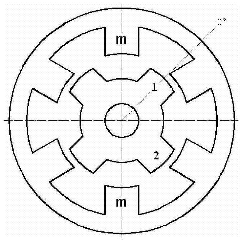
[0074] 2. The phase maximum inductance position of the switched reluctance motor in this embodiment is Figure 9 When the salient poles of the stator and rotor are shown relative to each other, the position of the minimum inductance of the phase is Figure 7 or Figure 11 The positions where the salient poles of the stator are facing the centers of two adjacent rotors are shown.

[0075] 3. In this embodiment, the cut-off angle of the switched reluctance motor is fixed at Figure 8 The 20° position prior to the maximum inductance position shown is not adjusted.

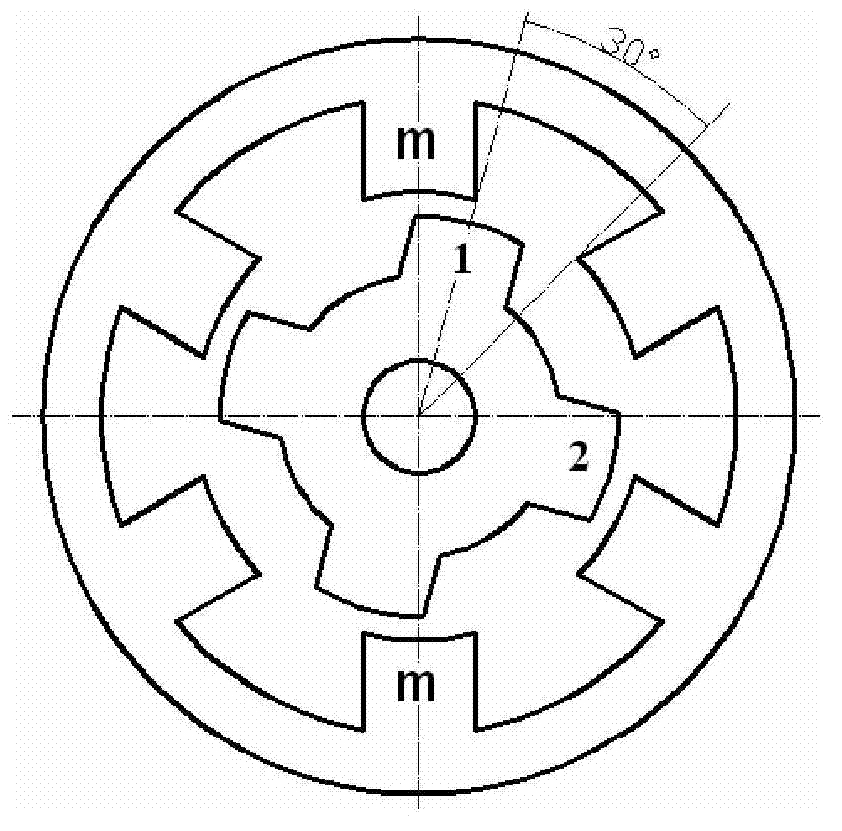
[0076] 4. In this embodiment, when the switched reluctance motor decelerates or brakes, the m phase is turned on after the maximum inductance position is 30°; At the turn-on...


PUM


Abstract

The invention discloses a method capable of reducing a torque tracking error of a switched reluctance motor. The method is characterized in that a flexible torque distribution mode is adopted to control an instantaneous torque, and the degree of the torque tracking error, which serves as a control variable, is limited through the online regulation of a turn-on angle, so as to allow the instantaneous torque output by the motor to track a reference torque in a small deviation manner as far as possible, so that both torque ripple and noise of the motor are reduced, and the smooth operation of the motor is ensured.

Description

technical field [0001] The invention relates to a method for reducing the torque tracking error of a switched reluctance motor, belonging to the field of torque control of a switched reluctance motor. Background technique [0002] The switched reluctance motor has a simple and firm structure, low starting current, and high torque. It is a new type of motor with great potential, but its further application is limited due to its large torque ripple and noise. How to suppress the torque ripple of the motor has become a hot spot in the research of this kind of motor, and improving the torque ripple of the motor from the control strategy is a main research direction. [0003] In the existing technology, the traditional current chopping control (CCC), angle position control (APC) and voltage chopping control (PWM) do not take the instantaneous torque as the control variable, and cannot control the output torque well, which is easy to cause Larger torque ripple, the instantaneous ...

Claims


Application Information

Patent Timeline
Patent Type & Authority Applications(China)
IPC IPC(8): H02P6/10
Inventor 张炳力戚永武徐国胜
Owner HEFEI UNIV OF TECH
Why Eureka
Try Eureka