
Method for realizing upper and lower roller load balance control based on 6RA80 direct current speed regulator

A load balancing and control method technology, applied in the direction of electric speed/acceleration control, etc., can solve the problems of unbalanced load and incomplete synchronization of actual speed, etc., and achieve the effect of uniform output, fast response speed and high economic benefit

Active Publication Date: 2016-03-23
BEIJING ARITIME INTELLIGENT CONTROL
View PDF4 Cites 0 Cited by
  • Summary
  • Abstract
  • Description
  • Claims
  • Application Information

AI Technical Summary

Problems solved by technology

[0007] In order to solve the problem of unbalanced load on the upper and lower rollers caused by the incomplete synchronization of the actual speed of the upper and lower rollers in the prior art, the present invention proposes a load balance control method for the upper and lower rollers based on a 6RA80 DC governor

Method used


Image

  • Method for realizing upper and lower roller load balance control based on 6RA80 direct current speed regulator
  • Method for realizing upper and lower roller load balance control based on 6RA80 direct current speed regulator

Examples


Embodiment Construction

[0025] The present invention will be further described in detail with reference to the accompanying drawings and embodiments.

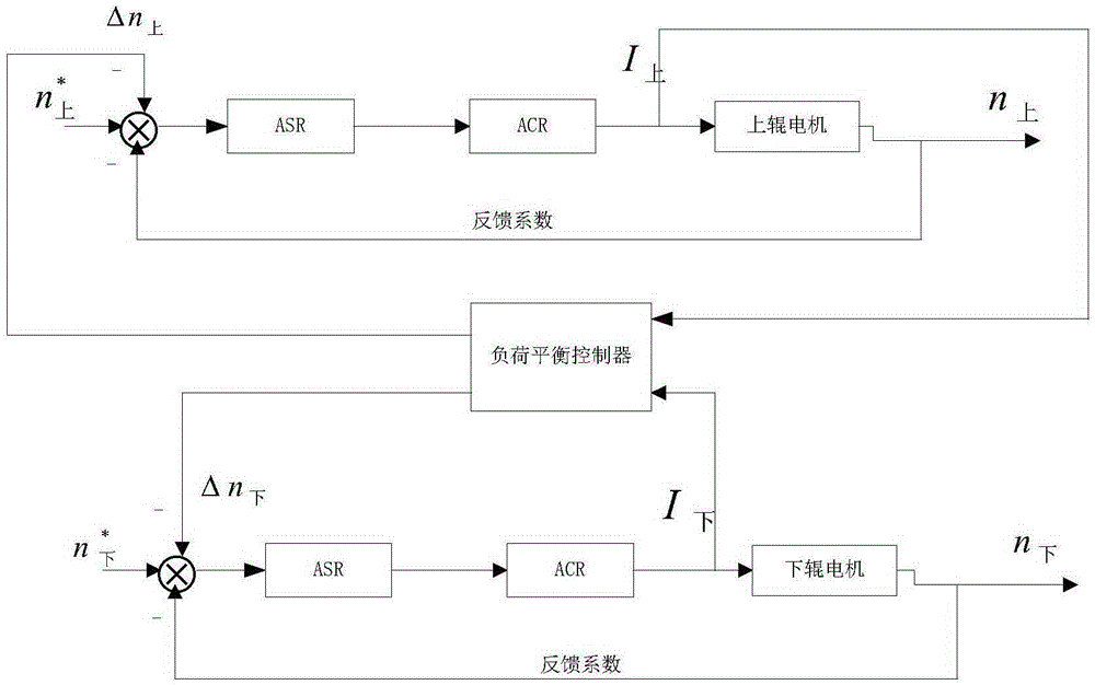
[0026] A method based on the DCC that comes with the 6RA80 DC speed controller to realize the load balance control method of the upper and lower rollers, based on the load balance control model, such as figure 1 As shown, the model includes: load balance controller, upper roller motor, lower roller motor and 6RA80 DC speed regulating device; 6RA80 DC speed regulating device integrates current regulator ACR and speed regulator ASR.

[0027] The load balance controller is respectively connected to the upper roller motor and the lower roller motor. The upper roller motor and the lower roller motor are controlled by their own independent 6RA80 DC speed control device. The upper roller motor and the lower roller motor drive the upper and lower rollers respectively.

[0028] The schematic diagram of the load balancing control model is as follows: figure 1 ...


PUM


Abstract

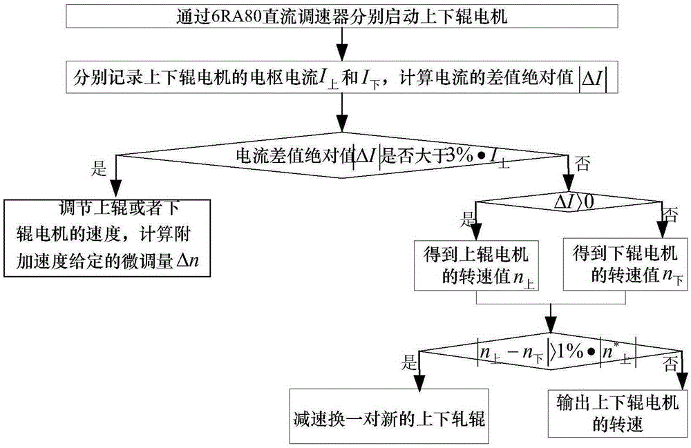
The invention discloses a method for realizing upper and lower roller load balance control based on a 6RA80 direct current speed regulator. The steps include: first starting upper and lower roller motors, recording armature current I<up> and I<down>, and calculating an absolute value of a current difference value |[delta]I|; then judging whether |[delta]I| is larger than 3%*I<up>; if yes, calculating a fine adjustment quantity [delta]n of additional given speed, and otherwise making no adjustment; then judging whether [delta]I in |[delta]I| is larger than 0, if yes, subtracting additional given speed from a given value of the speed of an upper roller to obtain a rotating speed value n<up> of the upper roller motor, and otherwise subtracting additional given speed from a given value of the speed of a lower roller to obtain a rotating speed value n<down> of the lower roller motor; and finally, judging whether an absolute value of a rotating speed difference value |n<up>-n<down>| of the upper and lower roller motors is larger than 1%*|n<up><*>|, if yes, decelerating and replacing with a new pair of upper and lower rollers, and otherwise outputting torque according to the rotating speed values n<up> and n<down> of the upper and lower roller motors, thereby realizing an upper and lower roller load balance. The method provided by the invention has the advantages of effectively controlling the output torque of the upper and lower rollers, and guaranteeing that a rolling torque load is equally distributed on the upper and lower working rollers.

Description

technical field [0001] The invention belongs to the field of metallurgical automation control, in particular to a method for realizing load balance control of upper and lower rollers based on a 6RA80 DC governor. Background technique [0002] When rolling with a large reduction, the output power of the drive motor is required to be relatively large. In order to reduce the load on the drive shaft of the motor, the upper and lower work rolls are driven separately, and because the drive torque of the motor shaft is relatively large, the general system design uses a DC motor. However, due to the limitation of commutation and other problems, it is impossible to increase the capacity of the DC machine. Therefore, in practical applications, in order to meet the power requirements of rolling, two motors are designed to drive two work rolls respectively. transfer method. [0003] Such a mechanical transmission method puts forward higher requirements for the control system of the upp...

Claims


Application Information

Patent Timeline
IPC IPC(8): G05D13/62
CPCG05D13/62
Inventor 张彦朱玲张湧郭艳兵周晶郭胜伟郭攀
Owner BEIJING ARITIME INTELLIGENT CONTROL
Learn More