Axial Rolling Bearings

A rolling bearing and axial technology, applied in the field of axial rolling bearings, can solve problems such as bearing disc wear, axial deep groove ball bearing piston compressor failure, etc.

Active Publication Date: 2016-01-20
SCHAEFFLER TECH AG & CO KG
View PDF7 Cites 0 Cited by
  • Summary
  • Abstract
  • Description
  • Claims
  • Application Information

AI Technical Summary

Problems solved by technology

Instead of a deliberate closeness to the raceway, the bearing balls thus only have a permanent point contact with an increased Hertzian pressure against the bearing disk, which can lead to increased wear of the bearing balls and associated bearing disks and Resulting in failure of axial deep groove ball bearings as well as the entire piston compressor

Method used


Image

  • Axial Rolling Bearings

Examples


Embodiment Construction

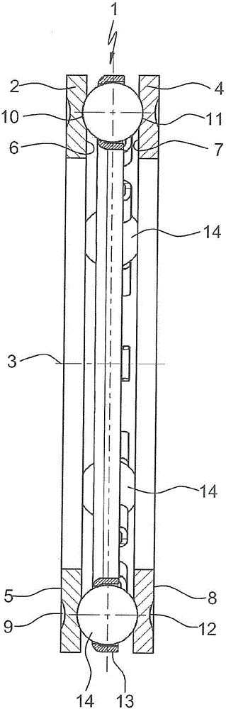
[0012] The drawing clearly shows an axial rolling bearing 1 configured as a single-row axial deep groove ball bearing, which has a first annular bearing disk 2 and is arranged at a distance from this bearing disk in a common The second annular bearing disk 4 on the central axis 3. The bearing disks 2 , 4 are formed here on their inner disk surfaces 6 , 7 with two groove-shaped rolling tracks 10 , 11 pointing toward one another, in which a large number of rollers arranged in rows roll. The rolling elements 14 are held at a uniform distance relative to one another by the bearing cage 13 .

[0013] Furthermore, it is clear from the figures that the two bearing disks 2 , 4 are configured according to the invention on their outer disk surfaces 5 , 8 with further running tracks on their inner disk surfaces 6 , 7 10, 11 Groove-shaped rolling tracks 9, 12 that are identical in terms of positioning, diameter and groove depth, via which the bearing discs 2, 4 can be selected independen...


PUM


Abstract

The invention relates to an axial rolling contact bearing (1) which is designed as an axial deep groove ball bearing acting on one side and which has a first circular-ring-shaped bearing disc (2) and a second circular-ring-shaped bearing disc (4) which is arranged at a distance from the former on a common centre axis (3), wherein the inner disc surfaces (6, 7) of the bearing discs (2, 4) are formed with mutually facing, groove-shaped raceways (10, 11), in which a multiplicity of rolling bodies (14), which are arranged in at least one row and are held at uniform distances from one another by at least one bearing cage (13), roll. According to the invention, the outer disc surfaces (5, 8) of the two bearing discs (2, 4) are formed with further groove-shaped raceways (9, 12) which are identical in position, diameter and groove depth to the raceways (10, 11) on the inner disc surfaces (6, 7) of said bearing discs and by means of which the bearing discs (2, 4) can be fitted, irrespective of a certain allocation during installation, at a designated bearing point either as a first or second bearing disc (2 or 4) and, in every possible fitting position with respect to each other, have the necessary number of mutually facing raceways (10, 11) for the rolling bodies (14).

Description

technical field [0001] The invention relates to an axial rolling bearing and can be used particularly advantageously in axial deep groove ball bearings acting on one side, as the invention is used, for example, to support rotors in compressors for domestic cooling appliances axis. Background technique [0002] Compressors for domestic cooling systems are mainly small single-cylinder piston compressors in which a gaseous cooling medium is sucked in and compressed. Piston compressors of this type essentially consist of a hermetically sealed housing, in which a cylinder is elastically mounted and accommodates the stator of the electric motor, which consists of a coil bundle. The rotor of the electric motor, which is arranged inside the stator and is configured with permanent magnets, is attached here to a central rotor shaft which is guided through the cylinder and has an eccentrically mounted crank at its end. Wave plate (Wellenscheibe) for pins (Kurbelzapfen). On this cran...

Claims


Application Information

Patent Timeline
Patent Type & Authority Patents(China)
IPC IPC(8): F16C19/10F16C33/58F16C43/04
CPCF16C19/10F16C33/586F16C43/04F16C2362/00
Inventor 沃尔夫冈·富格尔沃尔夫冈·布勃
Owner SCHAEFFLER TECH AG & CO KG
Why Eureka
Try Eureka