Camshaft adjuster having stator and rotor with spring receptacle concentric thereto

A technology of camshaft adjuster and accommodating part, which is applied in the directions of machines/engines, engine components, mechanical equipment, etc., can solve the problems of small spring torque, pin breakage, long manufacturing time, etc., and achieves high production cost and eliminates wrong assembly. Effect

Active Publication Date: 2020-01-24
SCHAEFFLER TECH AG & CO KG
View PDF6 Cites 0 Cited by
  • Summary
  • Abstract
  • Description
  • Claims
  • Application Information

AI Technical Summary

Problems solved by technology

[0003] The disadvantage of this is that only a small spring torque can be transmitted via the pins which have a small diameter compared to the rotor diameter
In addition, there is a risk of the pin breaking due to possible shear forces, e.g. due to the notch effect
[0004] In addition, the pins require more radial construction space and more manufacturing time, since their placement has to be precisely determined and the corresponding planes on the rotor have to be produced by turning

Method used


Image

  • Camshaft adjuster having stator and rotor with spring receptacle concentric thereto
  • Camshaft adjuster having stator and rotor with spring receptacle concentric thereto
  • Camshaft adjuster having stator and rotor with spring receptacle concentric thereto

Examples


Embodiment Construction

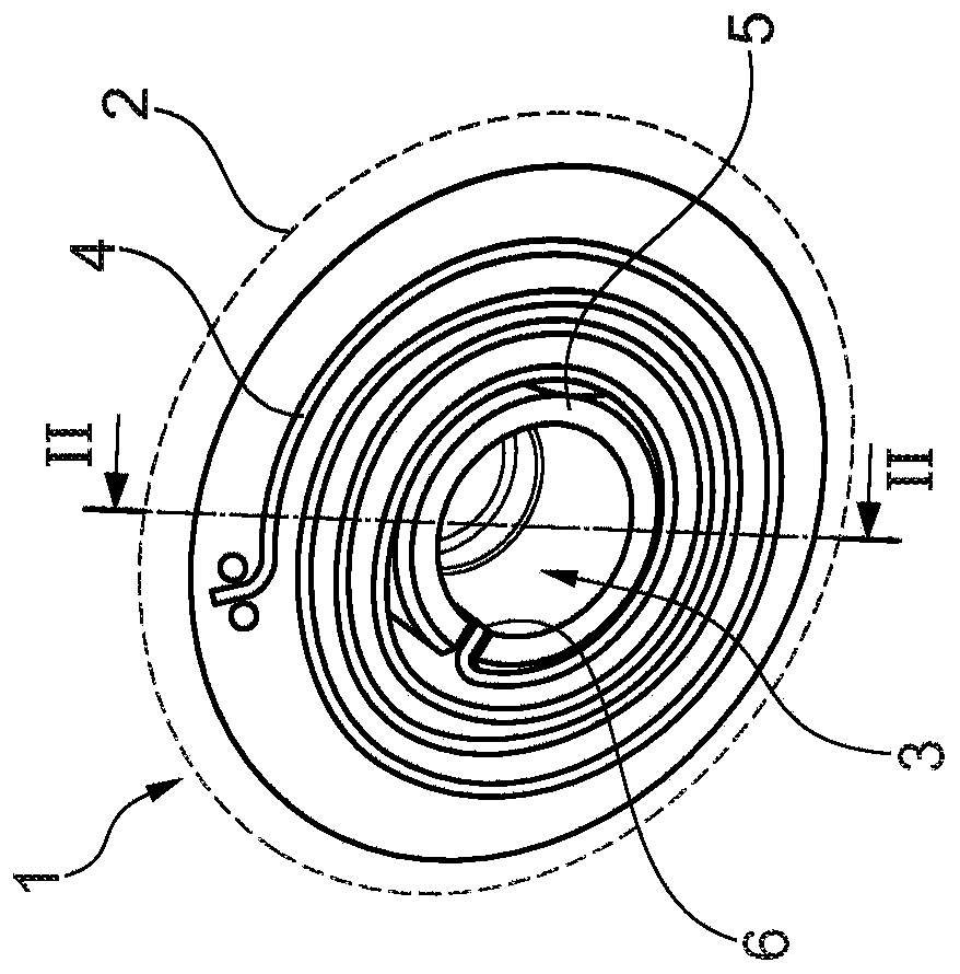
[0036] figure 1 The vane camshaft adjuster 1 is shown in FIG. It consists of a stator 2 and a rotor 3. A spring 4 is arranged between the stator 2 and the rotor 3. This spring is designed as a volute spring and is used to ensure that when there is no hydraulic pressure in the constructed hydraulic chamber, the stator 2 and the rotor 3 relatively occupy a predefined position.

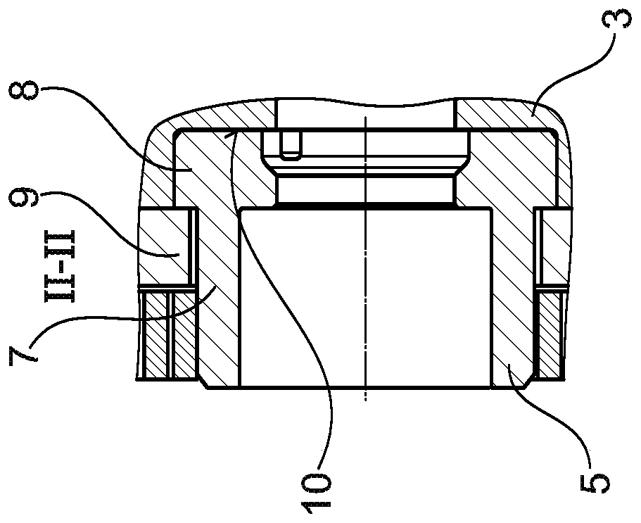
[0037] The camshaft adjuster 1 also has a spring receiving portion 5. The spring accommodating portion accommodates the radially inner end of the spring 4 via the slit 6. The section is shown along the line II-II, refer to figure 2 Explain it in more detail.

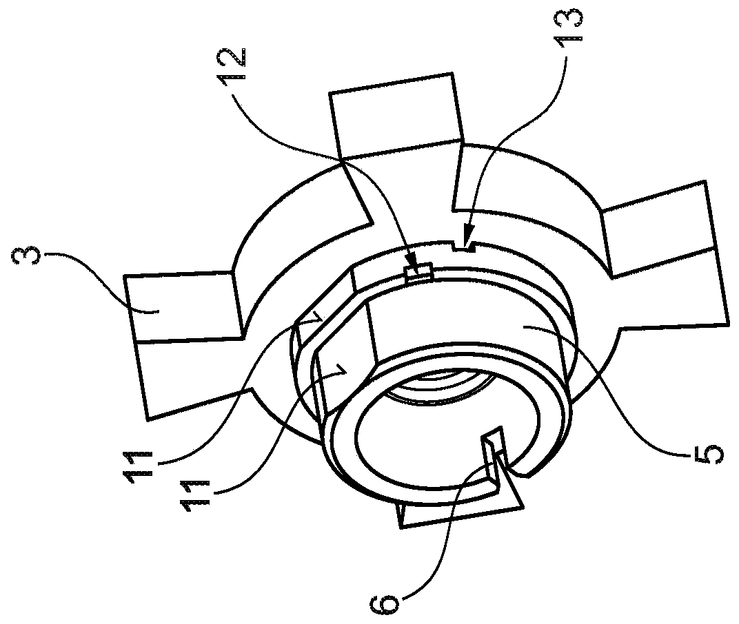
[0038] therefore, figure 2 It is shown that the spring receiving part 5 and the rotor 3 are designed as two independent components. The spring receptacle 5 is basically a sleeve-like component, which is designed concentrically with the rotor 3. The spring receiving part 5 is divided into a cylindrical section 7 and a ring section 8. The annular ...


PUM


Abstract

The invention relates to a vane-type camshaft adjuster for an internal combustion engine, having a stator and a rotor (3) which is arranged in the stator, can be rotated in relation thereto and is designed to adjust a phase angle of the camshaft, wherein a spring (4) is arranged between the stator and the rotor (3) to align the stator and the rotor (3) in relation to each other in a neutral position and the spring (4) is coupled to the rotor (3) by means of a spring receptacle (5), the spring receptacle (5) being designed as a sleeve-like spring receptacle (5) that is concentric to the rotor (3).

Description

Technical field [0001] The invention relates to a vane type camshaft adjuster for an internal combustion engine. It has a stator and a rotor arranged inside the stator and capable of rotating relative to the stator. The rotor is used to set the phase angle of the camshaft. At the same time, a spring, such as a volute spring, is arranged between the stator and the rotor so that the stator and the rotor are aligned with each other in the rest position. The spring is coupled with the rotor through the spring receiving part. Background technique [0002] Generic camshaft adjusters are known from the prior art. Therefore, German Patent Publication DE 10 2013 222819 A1 discloses a hydraulic camshaft adjuster and a rotor for the hydraulic camshaft adjuster, the rotor being used for form-locking connection with the camshaft. Each rotor has a base body on which blades can be installed or constructed to form a vane camshaft adjuster. On the side of the base body facing the camshaft, an...

Claims


Application Information

Patent Timeline
IPC IPC(8): F01L1/344
CPCF01L1/3442F01L2001/34483F01L2303/00
Inventor 克里斯蒂安·杜米特鲁·康斯坦丁内斯库克里斯蒂安·伯泽尔
Owner SCHAEFFLER TECH AG & CO KG
Why Eureka
Try Eureka