Dynamic knee joint, dynamic ankle joint prosthesis and dynamic lower-limb prosthesis

A technology of knee joint prosthesis and ankle joint, applied in the direction of prosthesis, medical science, measuring device, etc.

Inactive Publication Date: 2012-11-28
AVIATION MEDICINE INST AIR FORCE PLA
View PDF5 Cites 11 Cited by
  • Summary
  • Abstract
  • Description
  • Claims
  • Application Information

AI Technical Summary

Problems solved by technology

At the same time, a strength check is required

Method used


Image

  • Dynamic knee joint, dynamic ankle joint prosthesis and dynamic lower-limb prosthesis
  • Dynamic knee joint, dynamic ankle joint prosthesis and dynamic lower-limb prosthesis
  • Dynamic knee joint, dynamic ankle joint prosthesis and dynamic lower-limb prosthesis

Examples


Embodiment Construction

[0026] The present invention will be described in further detail below in conjunction with the accompanying drawings and specific embodiments.

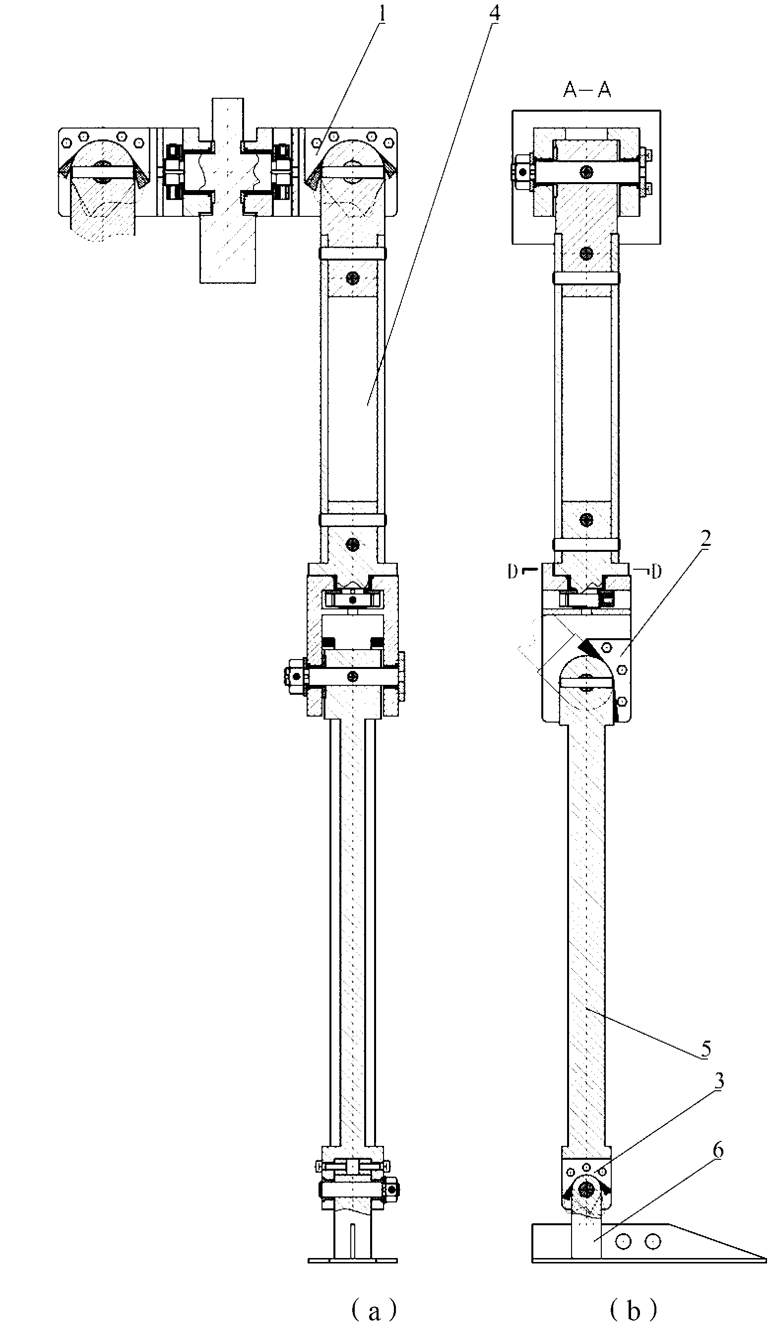
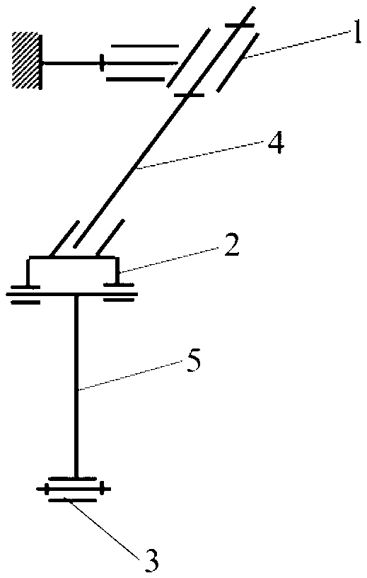
[0027] like figure 1 As shown, the present invention is a dummy lower limb, which can be used for pilot ejection dummy, automobile safety collision dummy and other robots. The present invention consists of knee joint 2, ankle joint 3, thigh 4, calf 5, foot 6 and various parts of simulated muscles 7, wherein the specific structure and movement of hip joint 1 formed between thigh and trunk (simulated pelvis) are realized (Specifically forward and backward swing and adduction and abduction movements) are protected in the inventor's other patent application, and will not be described in detail here. The present invention focuses on the part below the hip joint. In order to clearly represent the mechanical structure of the lower limbs, the simulated muscles are not in the figure 1 Indicated.

[0028] attached figure 1 It is the static...


PUM


Abstract

The invention discloses a dynamic knee joint, a dynamic ankle joint prosthesis, and a dynamic lower-limb prosthesis containing the dynamic knee joint and ankle joint prosthesis. The dynamic joint prosthesis comprises a U-shaped component, wherein a bottom plate of the U-shaped component is connected with an upper part component to form one rotation pair; two lateral plates of the U-shaped component are connected with a lower part component to form the other rotation pair; hard bosses are arranged on the bottom plate and the lateral plates of the U-shaped component for spacing, and a soft baffle is adhered to the outer side of each hard boss for buffer vibration; and an angular displacement sensor is arranged through a sensor assembly bracket to realize real-time measurement to joint angular displacement. According to the dynamic lower-limb prosthesis, motion in multiple degrees of freedom can be realized, the joint damping is adjustable, the limb posture can be maintained, and the motion angle can be measured in real time.

Description

technical field [0001] The invention belongs to the field of bionic structure design. It can be used in the design of the lower limb structure of robots, aviation ejection, car safety collision dummy and athlete's difficult movement design, and can also be used as a reference for lower limb rehabilitation training equipment. Background technique [0002] In the study of aviation ejection or automobile safety collision, dynamic simulation dummy is needed for experiments. The dummy structure system not only needs to realize the motion requirements and geometric shape requirements of the limbs, but also as a dynamic simulation dummy, the inertia parameters of the limbs must also conform to the characteristics of the human body. At the same time, the structural strength can meet the requirements of the mechanical load under the experimental conditions. Compared with the traditional static dummy, the geometry requirements are easy to meet. However, the motion, inertia paramete...

Claims


Application Information

Patent Timeline
Patent Type & Authority Applications(China)
IPC IPC(8): A61F2/64A61F2/66A61F2/60A61F2/62G01M7/08
Inventor 柳松杨王颉贾晓红
Owner AVIATION MEDICINE INST AIR FORCE PLA
Why Eureka
Try Eureka