Multi-link drive mechanism for harvester
A driving mechanism and multi-link technology, applied in the fields of harvesters, agricultural machinery and implements, applications, etc., can solve the problems of the complex transmission system of the whole machine and the difficulty in ensuring the relative positional relationship between the three, and achieve the movement requirements and simple structure. , the effect of high reliability
- Summary
- Abstract
- Description
- Claims
- Application Information
AI Technical Summary
Problems solved by technology
Method used
Image
Examples
Embodiment
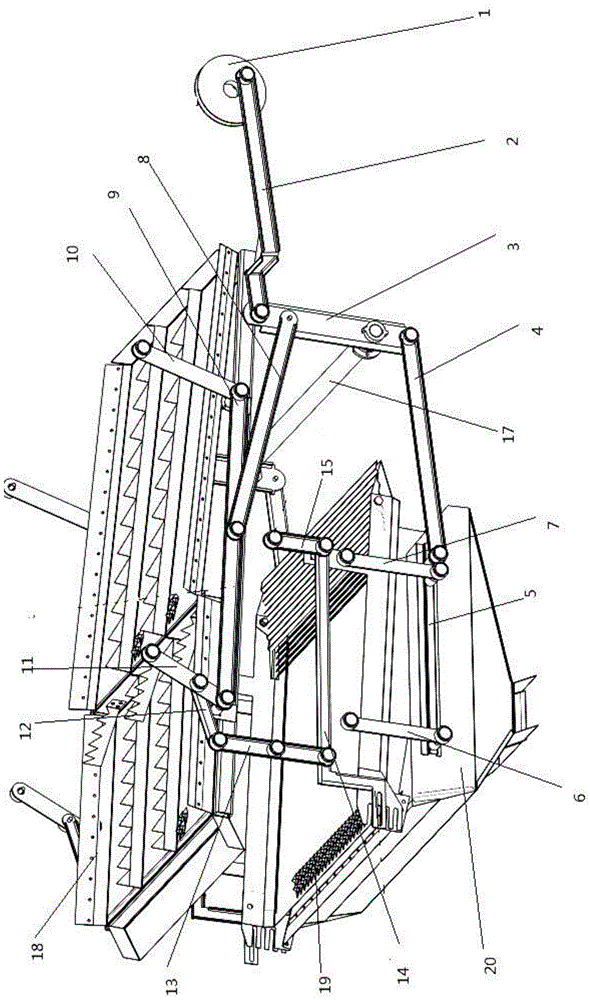
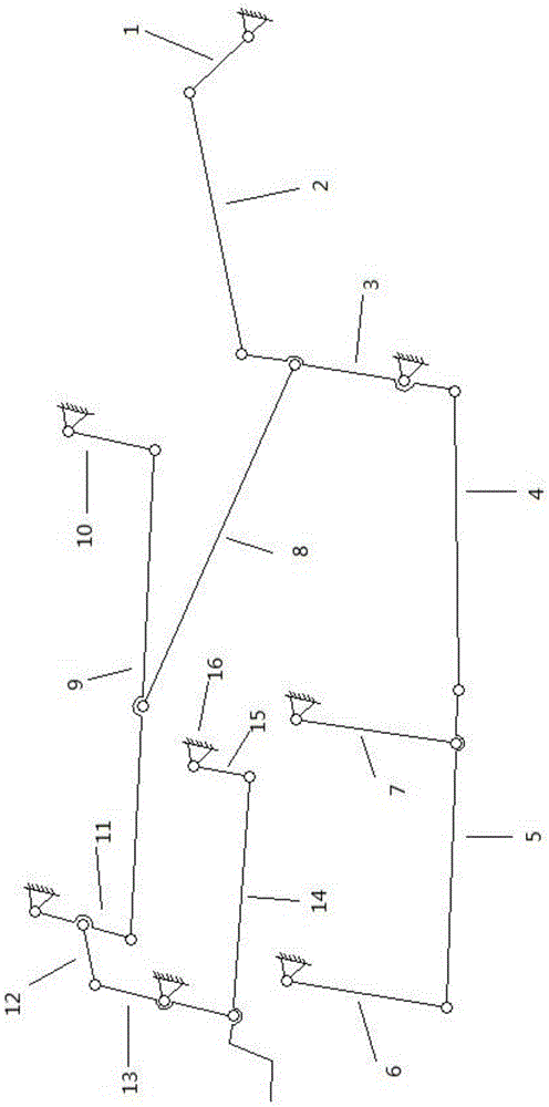
[0017] Such as Figure 1 ~ Figure 2 As shown, a multi-link drive mechanism used on harvesters includes crank wheel 1, draft screen 18, cleaning screen 19, grain collector 20, connecting rod A2, rocker A3, connecting rod B4, connecting rod C5, rocker B6, rocker C7, connecting rod D8, connecting rod E9, rocking rod D10, rocking rod E11, connecting rod F12, rocking rod F13, connecting rod H14, rocking rod H15, rack 16 and long axis 17, Draft screen 18, cleaning screen 19 and grain collector 20 are arranged sequentially from top to bottom; crank wheel 1 is hingedly mounted on the frame 16, one end of connecting rod A2 is hingedly mounted on crank wheel 1, and the other end of connecting rod A2 One end is hinged with one end of the rocker A3, and the rocker A3 is fixedly connected with the long shaft 17, and the long shaft 17 is connected with the frame 16 through a bearing; the other end of the rocker A3 is hinged with one end of the connecting rod B4, and connected The other end...
Embodiment 1
[0022] The driving mechanism of the multi-link driving mechanism used on the harvester is composed of crank crank wheel 1, and the multi-link driving mechanism used on the harvester also includes connecting rod A2, rocking rod A3, connecting rod B4, connecting rod C5, rocking rod B6, rocking rod C7, connecting rod D8, connecting rod E9, rocking rod D10, rocking rod E11, connecting rod F12, rocking rod F13, connecting rod H14, rocking rod H15 / frame 16 and long axis 17. Except crank wheel 1, connecting rod A2, major axis 17, all the other components are in the cleaning chamber (comprising draft sieve 18, cleaning sieve 19, grain collecting device 20, which are draft sieve 18, cleaning sieve 19, grain collecting device 20 as a whole) the other side has a symmetrical distribution, figure 1 , figure 2 No longer numbered. Its specific structure is: the crank wheel 1 is hinged with the frame 16, the crank crank wheel 1 is hinged with the connecting rod A2, the connecting rod A2 is...
Embodiment 2
[0024] figure 1 , figure 2 It can be seen that the multi-link drive mechanism used on the harvester is composed of crank wheel 1, connecting rod A2, rocking bar A3, connecting rod B4, connecting rod C5, rocking bar B6, rocking bar C7, Connecting rod D8, connecting rod E9, rocking bar D10, rocking bar E11, connecting rod F12, rocking bar F13, connecting rod H14, rocking bar H15, frame 16 and major axis 17 constitute. Since the parts other than the major axis 17, the crank wheel 1 and the connecting rod A2 are symmetrical, they are not shown separately in the figure.
[0025] from figure 1 It can be seen that, except crank wheel 1 and connecting rod A2, long axis 17, all the other components are in the cleaning room (comprising draft sieve 18, cleaning sieve 19, grain collector 20, which are draft sieve 18, cleaning sieve 19. The grain collector 20 as a whole) has a symmetrical distribution on the other side, and the power on the other side comes from the rocker A3 and is tr...
PUM
 Abstract
Description
Claims
Application Information
 - R&D
- Intellectual Property
- Life Sciences
- Materials
- Tech Scout
- Unparalleled Data Quality
- Higher Quality Content
- 60% Fewer Hallucinations
Browse by: Latest US Patents, China's latest patents, Technical Efficacy Thesaurus, Application Domain, Technology Topic, Popular Technical Reports.
© 2025 PatSnap. All rights reserved.Legal|Privacy policy|Modern Slavery Act Transparency Statement|Sitemap|About US| Contact US: help@patsnap.com


