
Lubricating roller

A technology of rollers and axles, applied in the field of mechanical parts, can solve the problems of easy failure and large friction of casters, and achieve the effect of reducing failure rate, reducing stress and prolonging service life

Inactive Publication Date: 2012-11-28
CHANGZHOU DONGWU CHAIN TRANSMISSION MFGCO
View PDF0 Cites 1 Cited by
  • Summary
  • Abstract
  • Description
  • Claims
  • Application Information

AI Technical Summary

Problems solved by technology

[0003] In order to overcome the disadvantages of the existing casters with high friction and easy failures, the present invention provides a lubricated roller

Method used


Image

  • Lubricating roller

Examples


Embodiment Construction

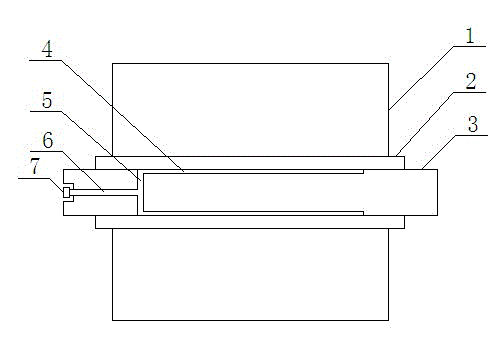
[0012] like figure 1 It is a schematic diagram of the present invention, a lubricating roller, including a wheel body 1, a shaft sleeve 2 and a wheel shaft 3, the wheel body 1 is set on the shaft sleeve 2, the shaft sleeve 2 is set on the wheel shaft 3, and the surface of the wheel shaft 3 is provided with two oil grooves 4. An oil delivery passage 5 is provided inside, and an oil injection passage 6 is provided at the end. The outer end of the oil injection passage 6 exposes the end face of the wheel shaft 3, and the inner end is vertically connected to the middle part of the oil delivery passage 5, and the oil delivery passage 5 is connected to the oil tank 4. The two oil grooves 4 are symmetrical about the axis of the axle 3 . Both ends of the oil delivery channel 5 are vertically connected to two oil grooves 4 respectively. The outer end of the oil injection passage 6 is provided with a filler nozzle 7 .

[0013] An oil groove 4 is added on the wheel shaft 3, and the rot...


PUM


Abstract

The invention relates to the machinery part field, especially to a lubricating roller. The lubricating roller comprises a roller body, a shaft sleeve and a wheel shaft. The roller body is sleeved on the shaft sleeve which is sleeved on the wheel shaft. The surface of the wheel shaft is provided with two oil grooves. The inner side of the wheel shaft is provided with an oil conveying channel. The end part of the wheel shaft is provided with an oil injection channel. The outer end of the oil injection channel is exposed out of the end face of the wheel shaft while the inner end is connected on the central part of the oil conveying channel in a perpendicular way. The oil conveying channel is connected with the oil grooves. A lubricating oil device is additionally equipped on the wheel shaft so as to lubricate the roller body when the roller body rotates on a roller shaft, and also alleviate friction and further reduce the stress exerted on a bearing support. The fault rate is thus decreased while the service lifetime is prolonged.

Description

technical field [0001] The invention relates to the field of mechanical parts, in particular to a lubricating roller. Background technique [0002] There are casters under the cargo box or container, so that the box can be dragged onto the freight car by means of a loading and unloading frame with a slope. The existing casters have a simple bushing structure. When the casters roll on the ground, the roller body rolls on the ground At the same time, the friction force between the roller body and the roller shaft is very large, and the stress produced by the support frame fixedly connected with the roller shaft at both ends is very large, which affects the work and is prone to failure. Contents of the invention [0003] In order to overcome the disadvantages of the existing caster wheels with high friction and easy failure, the invention provides a lubricated roller. [0004] The technical solution adopted by the present invention to solve its technical problems is: a lubri...

Claims


Application Information

Patent Timeline
IPC IPC(8): B60B33/00F16N1/00
Inventor 吴国平
Owner CHANGZHOU DONGWU CHAIN TRANSMISSION MFGCO
Learn More