
Gear oscillating bar type pneumatic spider robot

A spider robot and gear technology, applied in the field of bionic robots, can solve the problems of restricting crawling speed, poor obstacle crossing ability, and high terrain sensitivity, and achieve the effect of super obstacle crossing ability, low manufacturing cost, and easy popularization and application.

Inactive Publication Date: 2012-11-28
LIAONING TECHNICAL UNIVERSITY
View PDF9 Cites 7 Cited by
  • Summary
  • Abstract
  • Description
  • Claims
  • Application Information

AI Technical Summary

Problems solved by technology

For example, the Chinese invention patent (Patent No. 200410021277.9) discloses a cam-switching three-joint mechanical leg. The mechanical leg mainly uses cam switching to imitate human steps, but this leg is a bipedal walking mechanism, and its balance is critical. The terrain is highly sensitive, and the balance is difficult to control when walking on a strongly irregular surface; the Chinese invention patent (Patent No. 201010230995.2) discloses a spider robot that uses multiple servo motors to achieve pure electrical control of the spider's joints, but it only has Crawling function, and motor control restricts its crawling speed; Chinese invention patent (Patent No. 200810022629.0) discloses an elastic energy storage and energy release device for a bouncing robot. This device can only bounce and cannot adjust the posture of the body. If the body flips over in complex terrain, it will not be able to continue to bounce and store energy; Chinese invention patent (patent number 201010146485.7) discloses a bionic jumping robot based on a link mechanism, which consists of a crawler mechanism and an elastic potential energy-based link mechanism Realize walking and jumping functions, but the characteristics of the crawler walking mechanism determine that its ability to overcome obstacles is poor, and the jumping ability of its linkage mechanism is also limited, and there is no body posture adjustment function. If the robot jumps and lands in complex terrain, the body will Flips over, with the sole of the foot facing up, and will be unable to continue walking and jumping

Method used


Image

  • Gear oscillating bar type pneumatic spider robot
  • Gear oscillating bar type pneumatic spider robot
  • Gear oscillating bar type pneumatic spider robot

Examples


Embodiment Construction

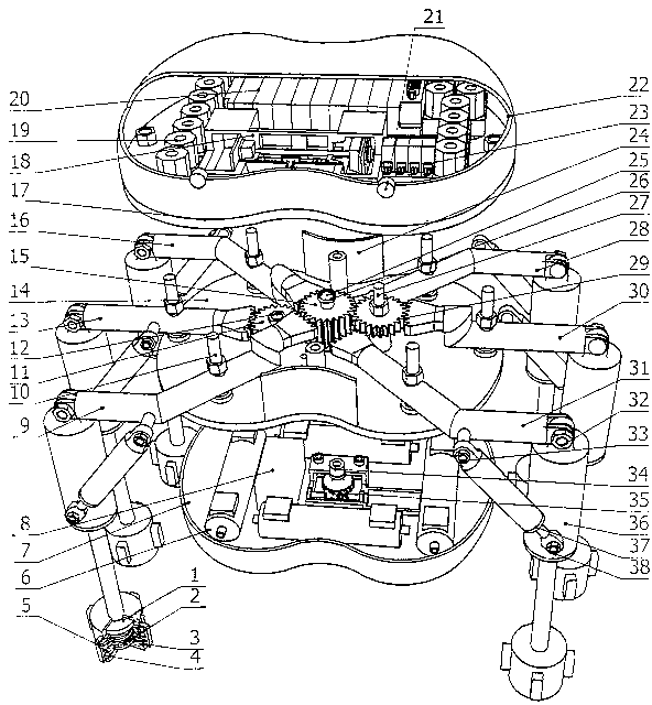
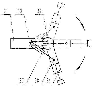
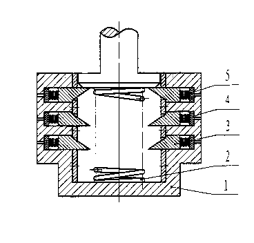
[0013] Example. Refer to attached Figure 1~4 , the gear pendulum type pneumatic spider robot is to be provided with central shaft 25 in the middle of lower base plate 14, on central shaft 25 with key dress drive gear 15, bearing 26 is housed on central shaft 25. Drive gear 15 is symmetrically staggeredly meshed to connect direction-changing gear one 11 and direction-changing gear two 29, and driving gear 15 is also meshed to connect symmetrical gear fork one 9, gear fork three 16, gear fork four 28, and gear fork six. 31, wherein the meshing position of driving gear 15 and reversing gear one 11, gear pendulum bar four 28, gear pendulum bar six 31 is in the lower horizontal plane, and driving gear 15 and reversing gear two 29, gear pendulum bar one 9, gear pendulum The engagement position of bar three 16 is in the upper horizontal plane. Reversing gear one 11 and reversing gear two 29 are contained in respectively on reversing gear shaft one 12, reversing gear shaft two 27, ...


PUM


Abstract

The invention belongs to a bionic robot and especially relates to a gear oscillating bar type pneumatic spider robot. A central shaft (25) is arranged in the middle of a lower base plate (14); a driving gear (15) is arranged on the central shaft (25); a first turning gear (11) and a second turning gear (29) are in symmetric engaging connection with the driving gear (15); a gear oscillating bar is in engaging connection with the driving gear (15); the first and second turning gear (11, 29) are arranged on first and second turning gear shafts (12, 27); the first and second turning gear shafts (12, 27) are arranged on the lower base plate (14); a shank cylinder (36) is hinged under each non-engaging end socket of the gear oscillating bar through a shank shaft (32); an electromagnetic diaphragm aerating pump (18) is arranged on an upper base plate (17); and the electromagnetic diaphragm aerating pump (18) is connected with a plurality of exhaust speed adjusting valves (19), a two-position two-way solenoid valve (23) and a three-position five-way solenoid valve (20). The gear oscillating bar type pneumatic spider robot can quickly walk, can horizontally and vertically cross obstacles, can quickly respond and can flexibly act.

Description

technical field [0001] The invention belongs to a bionic robot, in particular to a gear swing rod type pneumatic spider robot. Background technique [0002] At present, small ground mobile robots have good application prospects in dangerous and harsh environments such as military reconnaissance, interstellar exploration, nuclearization and pollution. Most of them use various motors to drive wheeled or crawler-type walking, but this It is difficult to move over obstacles whose height exceeds the limit, especially for complex terrain such as ridges, ditches, and soft sand. The way the legs move is better able to adapt to rough terrain than a wheeled or tracked structure because the legs have discrete footholds and a smaller contact area with the ground, even on extremely irregular surfaces , can also be achieved. However, the research on legged exercise machines is still in its infancy. The fundamental reason is that the principle, structure, control and production of legged...

Claims


Application Information

Patent Timeline
Patent Type & Authority Applications(China)
IPC IPC(8): B62D57/032
Inventor 刘强苏荣华席本强
Owner LIAONING TECHNICAL UNIVERSITY
Learn More