

Electric actuator with photoelectric positioning mechanism
A technology of electric actuators and positioning mechanisms, applied in mechanical equipment, engine components, valve operating/release devices, etc., can solve the problems of limited mechanical life, complicated installation and debugging process, complicated mechanical structure, etc., and achieve simple installation and debugging , Overcome the limitation of life and the complexity of installation and debugging, and reduce the effect of production components
Patent Information
- Authority / Receiving Office
- CN · China
- Patent Type
- Applications(China)
- Current Assignee / Owner
- Publication Date
- 2012-11-28
- Estimated Expiration
- Not applicable · inactive patent
Smart Images
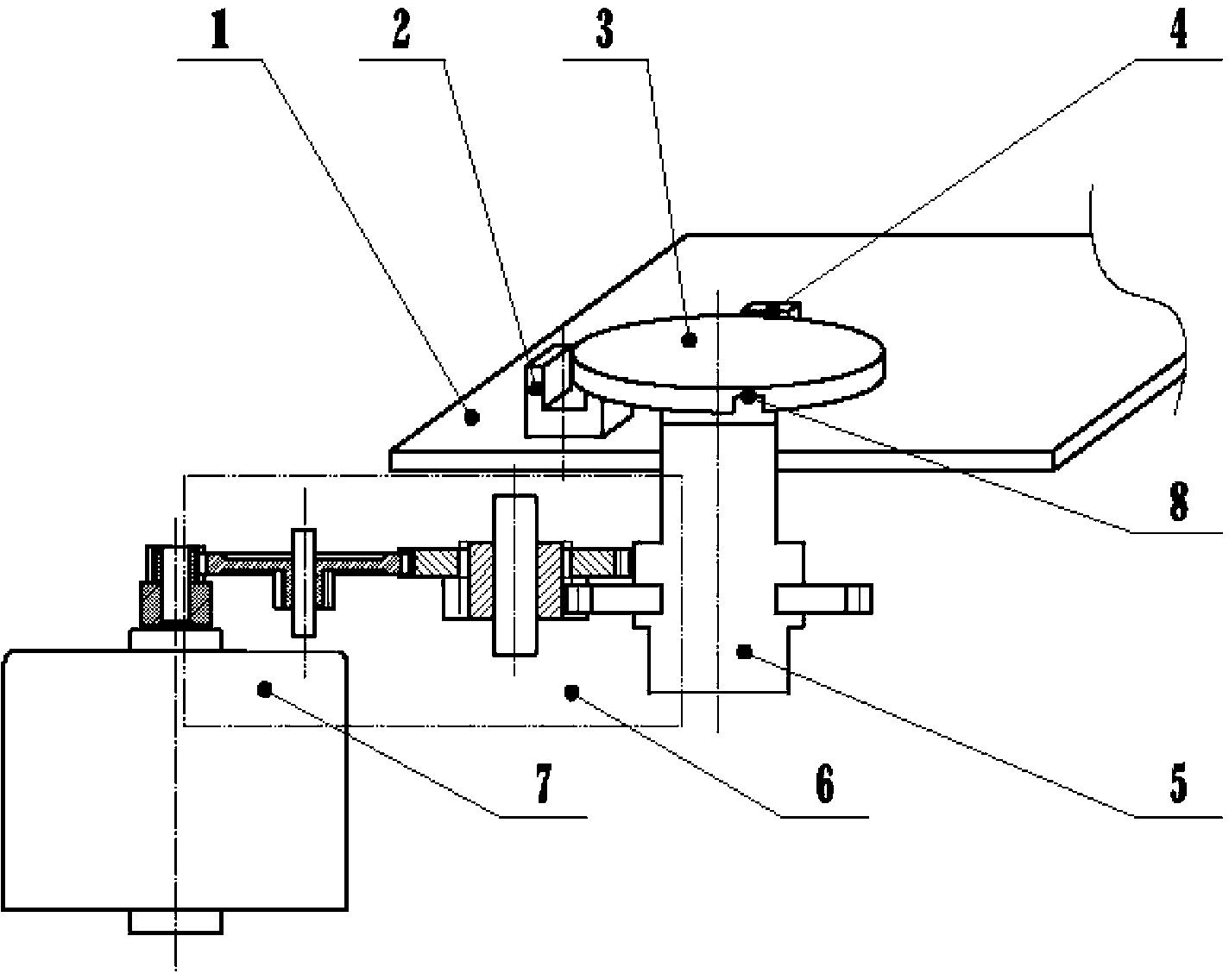
Figure 1 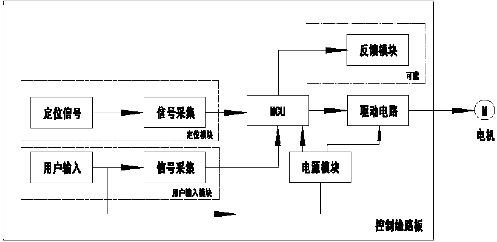
Figure 2 
Figure 3
Abstract
Description
technical field
[0001] The invention belongs to the field of electric actuators, in particular to an electric actuator with a photoelectric positioning mechanism. Background technique
[0002] An electric actuator is a drive device that provides linear or rotary motion, and its positioning methods mainly include reed positioning, micro switch positioning, etc. The structure of the electric actuator mainly includes a cam, a positioning mechanism group, and a control circuit board. The cam is vertically installed on the control circuit board. Touch the reeds or contacts of the positioning mechanism group, thereby generating a control signal.
[0003] The above-mentioned reed positioning and micro switch positioning have their own characteristics, but there are also different problems: although the structure of the reed positioning method is simple, the installation and debugging process is complicated, and the mechanical life is limited; the micro switch positioning method is...
Examples
Embodiment Construction
[0030] Embodiments of the present invention are described in further detail below in conjunction with the accompanying drawings:
[0031] An electric actuator with a photoelectric positioning mechanism, such as figure 1 As shown, it includes a control circuit board 1, a positioning mechanism, an output shaft 5, a transmission mechanism 6, and a motor 7. The motor is connected to the transmission mechanism and drives the output shaft to rotate through the transmission mechanism. The positioning mechanism includes a photoelectric switch 2 , the photoelectric switch 4 and the positioning disc 3, the positioning disc is fixed on the output shaft and rotates with the output shaft, a positioning disc gap 8 is arranged on the outer edge of the positioning disc, and the two photoelectric switches are installed on the control circuit board and located on the The position where the notch of the positioning disc rotates passes, and when the positioning disc rotates, two photoelectric swi...