Laser capable of regulating pulsewidth

A laser and pulse width technology, which is applied to lasers, laser components, phonon exciters, etc., can solve the problems of energy waste, large loss, and high cost, and achieve flexible pulse width adjustment, easy installation and debugging, and simple and convenient effects

Inactive Publication Date: 2007-12-19
BEIJING GK LASER TECH
View PDF1 Cites 14 Cited by
  • Summary
  • Abstract
  • Description
  • Claims
  • Application Information

AI Technical Summary

Problems solved by technology

[0006] The purpose of the present invention is to overcome the shortcomings of high cost, large loss, and serious energy waste in the prior art of using a Q-switched laser pl

Method used


Image

  • Laser capable of regulating pulsewidth

Examples


Embodiment 1

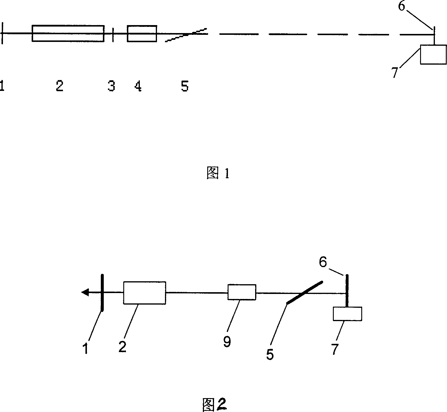
[0024] Referring to Figure 1, an electro-optic Q-switched pulse width-tunable laser is produced, including an output mirror 1, a laser rod 2, a 1 / 4 wave plate 3, a step-up electro-optic Q-switched Pockels cell 4, a polarizer 5, and a total reflection mirror 6. Moving stage 7. A pump source for exciting the laser rod 2. The polarization direction of the polarizer 5 is horizontal, and the angle between the plane of the polarizer 5 and the optical axis of the laser is Brewster's angle.

[0025] The material of the output mirror 1 is K9 glass or fused silica, coated with a dielectric film with a certain transmittance, for example, the transmittance T=90%. The material of the laser rod 2 is Nd:YAG, and the doping concentration is selected as 1%. The material of the step-up electro-optic Q-switched Pockels cell 4 is KD * P crystal, KDP or other Q-switching crystals can also be used, and the size only needs to be slightly larger than the diameter of the laser crystal rod. In this e...

Embodiment 2

[0031] Replacing the total reflection mirror 6 with a corner cube, and applying the corner cube in the laser cavity is competent for those skilled in the art, and the others are the same as in Embodiment 1. As disclosed in the document "Intense Lasers and Particle Beams, Volume 16, Issue 8, "Basic Characteristics of Corner Cube Laser Resonators", corner cube prisms have the advantages of self-stabilization, no need for debugging, and strong anti-detuning ability. Therefore, the laser in this embodiment has the advantages of self-stabilization, no need for debugging, strong anti-detuning ability, and the like. By operating the electric stage in a known manner, the corner cube is controlled to move along the optical axis, so as to realize the transformation of the length of the cavity. Because the length of the resonant cavity is the key factor affecting the laser pulse width, changing the cavity length can realize the change of the laser pulse width. When a short pulse needs t...

Embodiment 3

[0033] What embodiment 1 and embodiment 2 used all is the Pockels cell 4 of step-up electro-optic Q-switching. The Pockels cell 4 in this embodiment is a step-down electro-optic Q-switched Pockels cell, as shown in FIG.


PUM


Abstract

This invention discloses a laser realizing tuning of Q-switched pulse width including: an output mirror, a laser rod, a Pockels cell, a polaroid and a totally reflecting mirror set orderly on a same line in co-optical axis, a pump source for pumping said laser rod, a moving desk for the mounting the totally reflecting mirror to move it to-and-fro along the optical axis and alter length of a laser cavity.

Description

technical field [0001] The invention relates to pulsed laser technology, in particular to a laser capable of realizing laser Q-switching with tunable pulse width. Background technique [0002] With the rapid development of laser technology, laser technology plays an increasingly important role in various fields, from military to civilian, from scientific research to teaching, from industry to agricultural and sideline industries and many other fields. At the same time, in engineering applications, the requirements for laser reliability, engineering, stability, assembleability, versatility, and easy operation are getting higher and higher. [0003] The existing laser output with a single pulse width cannot meet the application requirements in many cases. At present, the scheme of realizing adjustable pulse width is mainly realized by chopper switch outside the laser resonator. This scheme with tunable pulse width has several disadvantages: First, this scheme can only realize...

Claims


Application Information

Patent Timeline
IPC IPC(8): H01S3/08H01S3/10H01S3/105H01S3/106H01S3/11H01S3/00
Inventor 樊仲维崔建丰裴博薛岩
Owner BEIJING GK LASER TECH
Why Eureka
Try Eureka