Mechanical conveying mechanism

A technology of mechanical feeding and racking, applied in the direction of conveyor objects, transportation and packaging, etc., can solve the problems of difficult maintenance, complex structure, easy damage of structure, etc., and achieve the effect of easy maintenance

Inactive Publication Date: 2015-01-07
CHONGQING SHUANGSHI MOTORCYCLE MFG
View PDF0 Cites 8 Cited by
  • Summary
  • Abstract
  • Description
  • Claims
  • Application Information

AI Technical Summary

Problems solved by technology

[0003] The structure of the existing feeding mechanism is too complicated. If the feeding mechanism needs to be adjusted in quantity, electromecha

Method used


Image

  • Mechanical conveying mechanism

Examples


Embodiment Construction

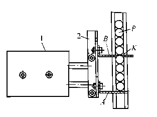
[0013] combined with figure 1 The mechanical feeding mechanism shown includes a frame and a chute P, and a double-axis cylinder 1 is connected by bolts on the frame. The double-axis cylinder 1 includes a cylinder cylinder, two piston rods, and a front plate 2 connected by bolts to the two piston rods. The front plate 2 is perpendicular to the ground, and the front plate 2 extends vertically to open a long hole. The length of the long hole is equal to the length of a workpiece. One side of the long hole is provided with a square mounting hole every other workpiece length. The front plate 2 Bolt the bottom of the long hole to connect the horizontal low-position baffle A, and the front plate 2 is bolted to a horizontal high-position baffle B in one of the installation holes in the long hole, and install it in the specific installation hole according to the needs How many workpieces are conveyed at a time depends. When deciding to change the conveying quantity, loosen the bolts th...


PUM


Abstract

The invention relates to mechanical devices related to conveying, particularly to a mechanical conveying mechanism. The mechanical conveying mechanism comprises a frame and a sliding groove; a double-shaft cylinder is fixed on the frame; a high baffle plate always penetrates the sliding groove no matter the double-shaft cylinder is located at the extension state or the retraction state; the high baffle plate is provided with a through hole for workpieces arranged in the sliding groove to pass through when the double-shaft cylinder is located at the extension state; a low baffle plate is used for penetrating and closing the sliding groove when the double-shaft cylinder is located at the extension state; the low baffle plate retreats from the sliding groove when the double-shaft cylinder is located at the retraction state. According to the mechanical conveying mechanism, the structure is simple and the conveying number of the workpieces can be controlled without mechanical and electrical equipment.

Description

technical field [0001] The invention relates to a mechanical device related to conveying, in particular to a mechanical feeding mechanism. Background technique [0002] The feeding mechanism is used for the transportation of pellets, powders, flakes, strips and other products. It is widely used in various industries. In today's society, more and more manufacturers adopt mechanized transportation. This method will replace human labor inevitably. It has high accuracy, saves time and labor, and greatly reduces labor intensity, reduces labor costs and saves human resources. It really achieves low cost and high return. In this era of rapid development, this kind of automation products will be favored and liked by more and more manufacturers. [0003] The structure of the existing feeding mechanism is too complicated. If the feeding mechanism needs to be adjusted in quantity, electromechanical control equipment must be added. Complex structure and mechanical and electrical equ...

Claims


Application Information

Patent Timeline
IPC IPC(8): B65G47/74
Inventor 陈厚智
Owner CHONGQING SHUANGSHI MOTORCYCLE MFG
Why Eureka
Try Eureka