Heat-conducting and heat-storing phase-change plate and preparation method thereof

A phase change and heat storage technology, applied in the field of heat dissipation, can solve the problems of electronic components such as difficult repair, difficult removal, leakage, etc., and achieve the effect of avoiding interface compatibility problems, increasing weight percentage, and enhancing heat transfer performance

Inactive Publication Date: 2020-06-05
GUANGZHOU SHIYUAN ELECTRONICS CO LTD
View PDF19 Cites 9 Cited by
  • Summary
  • Abstract
  • Description
  • Claims
  • Application Information

AI Technical Summary

Problems solved by technology

[0005] (1) The durability of phase change materials, that is, the physical and chemical properties are easy to degrade during the phase change cycle, which affects its heat storage and thermal conductivity
Some common heat-conducting phase-change materials on the market are prone to drying and cracking during medium and long-term use;
[0006] (2) The pollution of electronic components by phase change materials, because the materials after phase change have a certain fluidity, they are easy to leak from the matrix, immerse into the gaps of the devices, and cause pollution to the devices;
[0007] (3) It is relatively difficult to repair electronic components after using phase change materials. The phase change materials fully fill the surface and gaps of wetted devices, which are difficult to remove during the repair process, and are easy to damage electronic components, which greatly increases the cost of repair;
[0008] (4) The interface compatibility between phase change materials and electronic components. The phase change material formula involves materials with multiple components, and the difference in expansion coefficient between them and the device is likely to cause internal stress. The material also has the risk of chemical reaction with the surface of the device, which greatly affects the performance of electronic components

Method used


Image

  • Heat-conducting and heat-storing phase-change plate and preparation method thereof
  • Heat-conducting and heat-storing phase-change plate and preparation method thereof
  • Heat-conducting and heat-storing phase-change plate and preparation method thereof

Examples


Embodiment 1

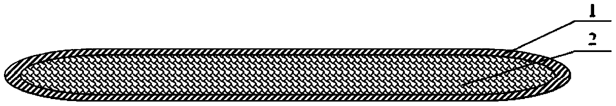
[0040] The heat conduction heat storage phase change plate of this embodiment, such as figure 1As shown, it includes a phase change plate shell 1 and a phase change composite material 2. The phase change plate shell 1 encloses a closed cavity, and the phase change composite material 2 is filled in the cavity. The phase change plate shell 1 The material is copper, and the phase-change composite material 2 is composed of the following raw materials in parts by weight: 500 parts of refined paraffin wax for phase-change materials, and 100 parts of a mixture of alumina and graphene at a weight ratio of 30:1 as a heat-conducting filler.

Embodiment 2

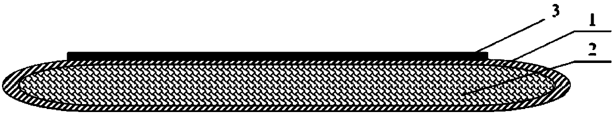
[0042] The heat conduction heat storage phase change plate of this embodiment, such as figure 2 As shown, it includes a phase change plate shell 1 and a phase change composite material 2. The phase change plate shell 1 encloses a closed cavity, and the phase change composite material 2 is filled in the cavity. The phase change plate shell 1 An adhesive layer 3 is arranged on one surface of the phase change plate shell 1, and the material of the phase change plate shell 1 is copper, and the phase change composite material is composed of the following raw materials in parts by weight: 600 parts of refined paraffin wax for the phase change material, aluminum oxide for thermal conductivity, The mixture of graphene and carbon nanotubes in a weight ratio of 30:1:1 is 100 parts in total.

Embodiment 3

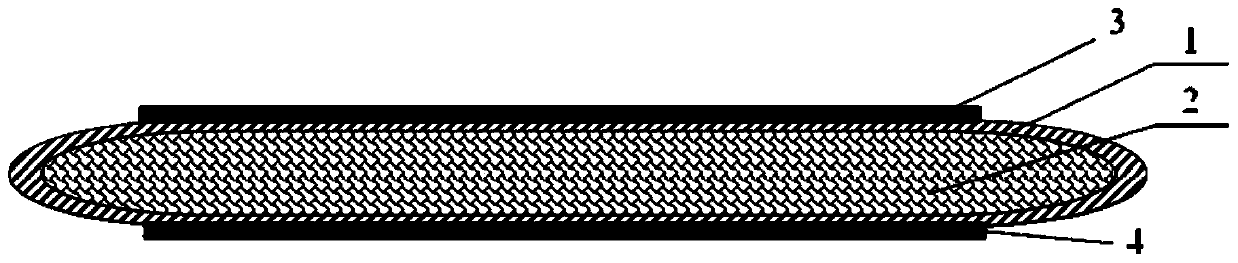
[0044] The heat conduction heat storage phase change plate of this embodiment, such as figure 2 As shown, it includes a phase change plate shell 1 and a phase change composite material 2. The phase change plate shell 1 encloses a closed cavity, and the phase change composite material 2 is filled in the cavity. The phase change plate shell 1 An adhesive layer 3 is arranged on one surface of the phase change plate, the shell material of the phase change plate is copper, and the phase change composite material is composed of the following raw materials in parts by weight: 60 parts of silicon rubber for the base material, 400 parts of refined paraffin wax for the phase change material, The thermally conductive filler is 150 parts of a mixture of alumina and graphene at a weight ratio of 30:1, 8 parts of a silane coupling agent, and 2 parts of a thermal stabilizer calcium stearate.


PUM


Abstract

The invention relates to the technical field of heat dissipation. The invention provides a heat-conducting and heat-storing phase-change plate and a preparation method thereof. The heat-conducting andheat-storing phase-change plate comprises a phase change plate shell and a phase change composite material. A closed containing cavity is defined by the phase change plate shell. The phase-change composite material is filled in the containing cavity, the phase change plate shell is made of a heat conduction material, and the phase change composite material comprises the following raw material components in parts by weight: 300-600 parts of a phase change material, 100-250 parts of a heat conduction filler, 0-80 parts of a base material, 0-15 parts of a coupling agent and 0-3 parts of a heat stabilizer. The heat-conducting and heat-storing phase-change plate is high in phase change latent heat, large in heat conduction coefficient, good in durability, free of toxicity and corrosion to electronic components, easier to clean and repair, good in interface compatibility, low in manufacturing cost, simple in formula and convenient to use.

Description

technical field [0001] The invention belongs to the technical field of heat dissipation, and in particular relates to a heat conduction heat storage phase change plate and a preparation method thereof. Background technique [0002] With the rapid development of electronic integration technology, electronic equipment is developing in the direction of miniaturization and thinning, and the integration degree of the system is getting higher and higher. On the other hand, with the application of high-power components in electronic equipment, the thermal power consumption increases sharply, and the resulting heat does not have enough space to dissipate, which directly affects the working performance and service life of the product. Statistics show that more than 40% of the The reliability (life) failure of electronic products is caused by the problem of temperature rise. With the advent of the 5G era, the heat dissipation task of electronic products has become particularly severe...

Claims


Application Information

Patent Timeline
Patent Type & Authority Applications(China)
IPC IPC(8): C09K5/06C09K5/14C08L91/06C08L83/04C08L9/02C08L11/00C08L71/02C08L63/00C08K13/02C08K5/098C08K3/22C08K3/04C08K13/04C08K7/24C08K3/38C08K3/34
CPCC08K3/22C08K2003/2227C08K2003/387C08K2201/011C08L71/02C08L91/06C08L2203/20C09K5/063C09K5/14C08K3/041C08K3/042C08L83/04C08K13/02C08K5/098C08L9/02C08K13/04C08K7/24C08K3/38C08L11/00C08K3/34C08L63/00
Inventor 万虎冯先强
Owner GUANGZHOU SHIYUAN ELECTRONICS CO LTD
Why Eureka
Try Eureka