Low-temperature phase-change heat accumulator

A low-temperature phase change and regenerator technology, which is applied in the direction of heat storage equipment, indirect heat exchangers, heat exchanger types, etc., can solve the problem of poor operating performance, low heat storage and slow heat storage and discharge speed of phase change regenerators and other problems, to achieve the effect of good material stability, elimination of supercooling phenomenon, and improvement of COP

Inactive Publication Date: 2014-01-15
TAIYUAN UNIV OF TECH +2
View PDF8 Cites 9 Cited by
  • Summary
  • Abstract
  • Description
  • Claims
  • Application Information

AI Technical Summary

Problems solved by technology

[0006] The invention provides a low-temperature phase-change heat accumulator, which mainly solves the technical problems of poor operating performance of an air source heat pump in a low-temperature environment, low heat storage capacity of the phase-change heat accumulator, and slow heat storage and discharge speed.

Method used


Image

  • Low-temperature phase-change heat accumulator

Examples


Embodiment Construction

[0018] The invention will be further described below in conjunction with the accompanying drawings and specific embodiments, and the invention is not limited thereto.

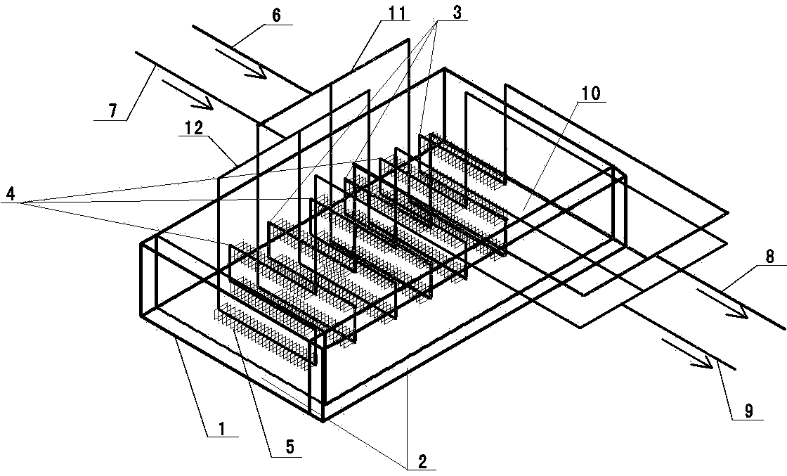
[0019] Such as figure 1 As shown, a low-temperature phase change heat accumulator provided by the present invention includes a box body, which can be made of steel, polyurethane foam insulation material is arranged in the interlayer of the box body, and serpentine metal pipe rows are arranged inside the box body, including storage The heat pipe row and the heat release pipe row, the working medium in the tube is refrigerant fluid. The two tube rows are arranged alternately, and metal fins are set at intervals on the two metal tube rows. In this embodiment, it is preferably a rectangular structure with a size of 55×26×0.3mm and a fin pitch of 5mm. The structure and size layout greatly increase the heat storage area and heat release area, increase the heat storage, and enhance the heat storage and heat release p...


PUM


Abstract

The invention provides a low-temperature phase-change heat accumulator which comprises a tank body and a snakelike metal pipe row. The snakelike metal pipe row is arranged in the tank body, metal fins are arranged on the snakelike metal pipe row in a sleeved mode at intervals, the snakelike metal pipe row comprises heat accumulation pipe row bodies and heat releasing pipe row bodies, the heat accumulation pipe row bodies and the heat releasing pipe row bodies are alternatively arranged, the heat accumulation pipe row bodies are connected with a heat accumulation refrigerant loop of a heat accumulation evaporation type air source heat pump through liquid inlet pipes and liquid outlet pipes of the heat accumulation pipe row bodies, the heat releasing pipe row bodies are connected with a heat releasing refrigerant loop of the heat accumulation evaporation type air source heat pump through liquid inlet pipes and liquid outlet pipes of the heat releasing pipe row bodies, the positions between the heat accumulation pipe row bodies and the liquid inlet pipes of the heat releasing pipe row bodies and between the heat accumulation pipe row bodies and the liquid outlet pipes of the heat releasing pipe row bodies are respectively provided with a heat accumulation header, the positions between the heat releasing pipe row bodies and the liquid inlet pipes of the heat releasing pipe row bodies and between the heat releasing pipe row bodies and the liquid outlet pipes of the heat releasing pipe row bodies are respectively provided with a heat releasing header, heat preservation materials are arranged in an interlayer of the tank body, and the interior of the tank body is filled with composite phase-change heat accumulation materials. The low-temperature phase-change heat accumulator is mainly used in an air source heat pump unit technological process, can serve as a heat accumulator or a subcooler or an auxiliary evaporator, and can carry out heat accumulation and heat releasing at the same time. The heat supply coefficients of a heat pump unit can be improved, and the operation performance of the air source heat pump unit in a low-temperature environment is remarkably improved.

Description

technical field [0001] The invention relates to an energy storage and release device, in particular to a low-temperature phase-change heat accumulator with a double serpentine-fin tube row structure. Background technique [0002] Phase change heat storage is to store or release heat by absorbing or releasing heat energy when the phase change material undergoes a phase change. It has many advantages such as large heat storage per unit volume, small temperature fluctuation, and good safety. There are many research results on phase change heat storage materials, but the main problem is that the stability of the materials is average, and the heat storage capacity will decline to varying degrees after repeated heat storage and discharge. Common phase change heat storage materials include paraffin, sulfate, nitrate, and fluoride. The phase change thermal storage and cold storage heat exchangers currently studied are mainly composed of plate type phase change heat exchangers, rib ...

Claims


Application Information

Patent Timeline
Patent Type & Authority Applications(China)
IPC IPC(8): F28D20/02F25B30/06
CPCY02E60/14
Inventor 马素霞李永辉张建春武卫红刘建华谢豪
Owner TAIYUAN UNIV OF TECH
Why Eureka
Try Eureka