
Support structure for steam generator in nuclear station and steam generator

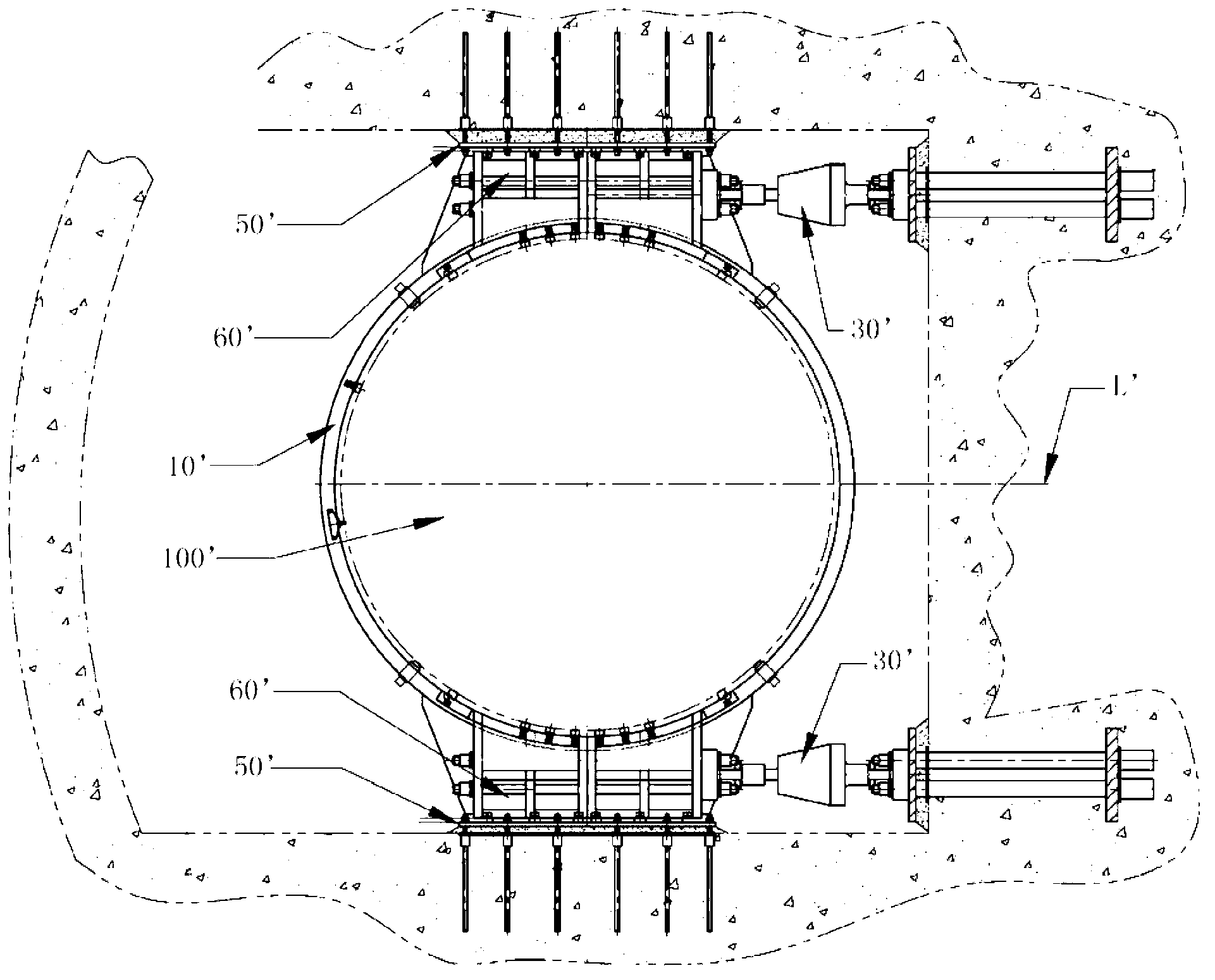
A technology for steam generators and supporting structures, applied in steam generation, steam generation methods, detailed information of nuclear power plants, etc., can solve problems such as reducing the anti-seismic performance of the main system of reactor coolant, and achieve the effect of eliminating gaps and improving anti-seismic performance

Active Publication Date: 2012-11-28
中广核工程有限公司 +1
View PDF3 Cites 13 Cited by
  • Summary
  • Abstract
  • Description
  • Claims
  • Application Information

AI Technical Summary

Benefits of technology

This innovation allows for better control over the movement or vibration caused by heavy loads on equipment used during operation without causing damage. It also enhances the stability of the steel reinforced plastic (CRP) shell design that forms part of the heat exchanger's core. Overall, it provides technical benefits such as increased safety, reduced maintenance costs, enhanced efficiency, etc., which can lead to more reliable operations within an advanced thermal energy technology facility.

Problems solved by technology

This patented describes how the problem addressed during construction work relating to preventing damage caused by high pressure water hammer events from causing ruptures in pipes and turbines within power plants. Existing designs have issues where they may lead to insufficient stability and reliance over long periods of time.

Method used


Image

  • Support structure for steam generator in nuclear station and steam generator
  • Support structure for steam generator in nuclear station and steam generator
  • Support structure for steam generator in nuclear station and steam generator

Examples


Embodiment 1

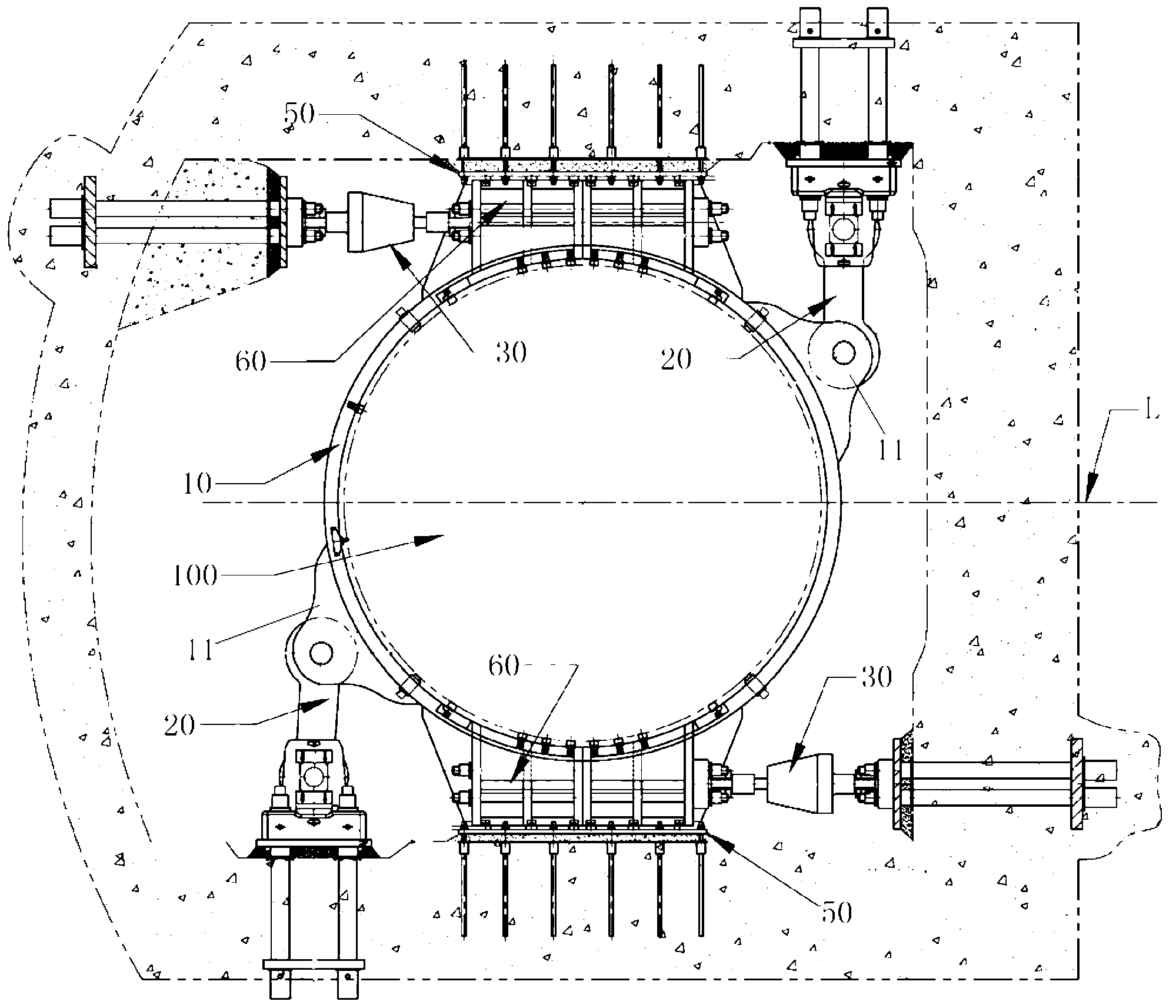
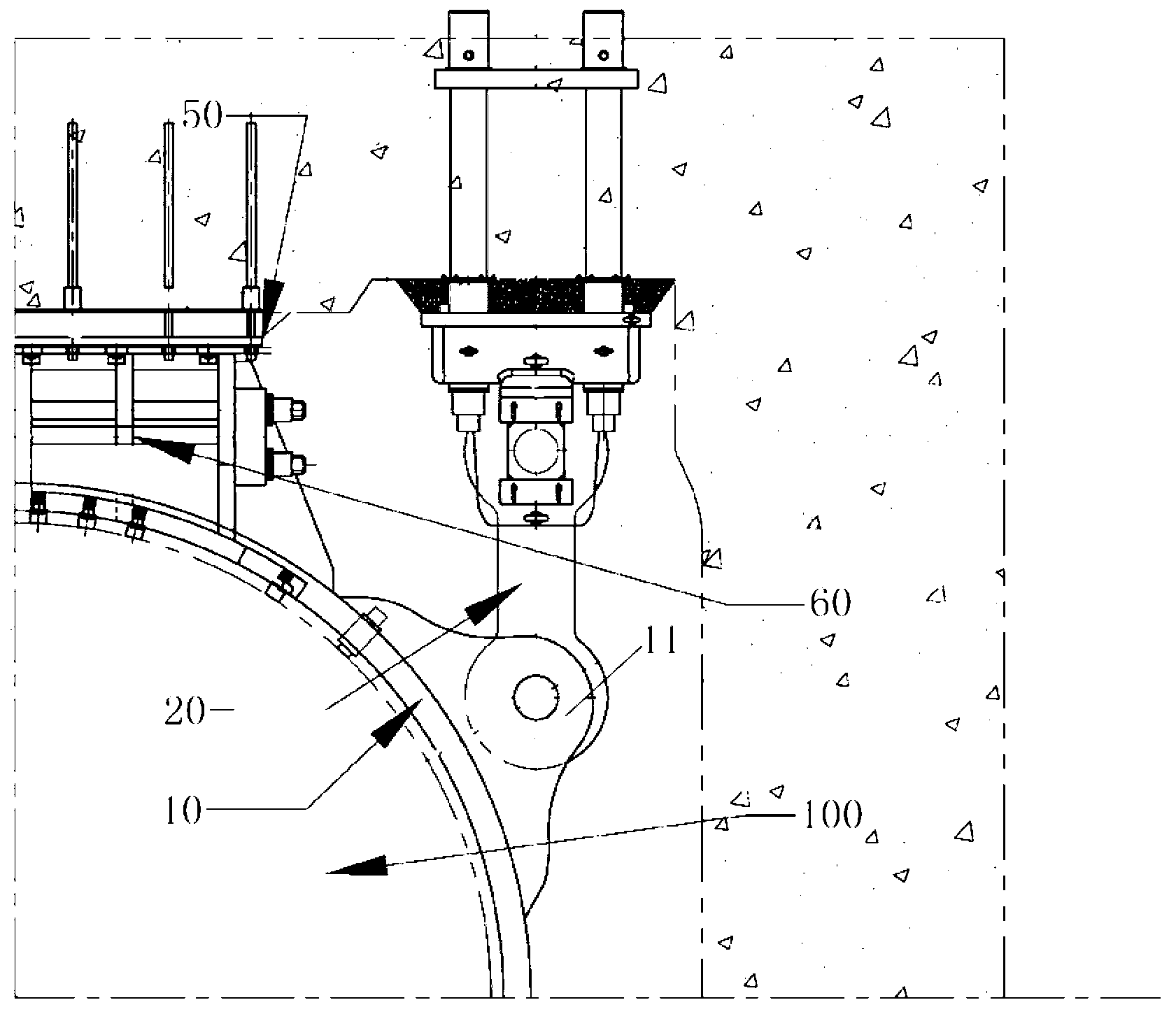
[0042] Such as figure 2 , image 3 As shown, in a nuclear power plant steam generator support structure of the present invention, it includes a swing tie rod 20, a damper 30, and a support ring 10 that surrounds the steam generator 100. On the support ring 10, a Connecting lug 11, one end of the swing rod 20 is connected to the connecting lug 11 on the support ring 10, and the other end of the swing rod 20 is connected to the concrete side wall of the room of the steam generator.

[0043] Further, the number of the swing pull rods 20 is two, which are respectively installed on the upper right and lower left parts of the support ring 10 and the two are set opposite to each other. The direction of the axis L of the hot section is approximately vertical.

[0044] Further, the other end of the swing rod 20 is connected to the anchor support 50 on the concrete side wall of the room.

[0045] Further, the number of the dampers 30 is four, and the four dampers 30 are respectively...

Embodiment 2

[0052] The difference from Example 1 is that, as Figure 4 to Figure 6 As shown, the support structure of the above-mentioned steam generator adopts a layered structure, and the upper horizontal support structure of the steam generator is split and arranged at two elevations respectively. Two swing tie rods 20 are arranged along the direction perpendicular to the axis L of the hot section of the main pipeline at the horizontal support elevation position on the upper part of the steam generator 100 .

[0053] Further, the number of the swing tie rods 20 is two, which are respectively arranged on the upper part of the steam generator 100 and both of them are arranged in the same direction; The direction of the segment axis L is approximately vertical; two dampers 30 are arranged above the two swing rods 20 and along the axis L of the hot segment of the main pipeline. This structure can be used to better improve the anti-seismic performance.

[0054] Further, as Figure 5 As sh...


PUM


Abstract

The invention relates to a support structure for a steam generator in a nuclear station. The support structure comprises at least two groups of oppositely arranged swing pull rods (20) and at least two groups of oppositely arranged dampers (30); the extension direction of the swing pull rods (20) is vertical to the extension direction of the dampers (30), one end of each swing pull rod (20) and one end of each damper (30) are respectively connected onto mutually perpendicular concrete side walls of a steam generator room, the other end of the swing pull rod (20) and the other end of the damper (30) are respectively connected with the steam generator (100). The invention further relates to the steam generator in the nuclear station. The support structure is directly connected onto the concrete anchor walls by the swing pull rods, so that the gaps between a horizontal support at the upper part of the steam generator and the concrete walls are eliminated, and the seismic performance of a reactor coolant system is improved.

Description


Claims


Application Information

Patent Timeline
Owner 中广核工程有限公司
Learn More