Apparatus working state diagnostic method and apparatus working state diagnostic device

A technology of working state and diagnosis method, applied in the direction of measuring devices, instruments, measuring electricity, etc., can solve the problem of increasing the number of settings

Inactive Publication Date: 2012-11-28
PANASONIC INTELLECTUAL PROPERTY MANAGEMENT CO LTD
View PDF4 Cites 4 Cited by
  • Summary
  • Abstract
  • Description
  • Claims
  • Application Information

AI Technical Summary

Problems solved by technology

Thus there is the following problem: with the reduction of CO 2 The number of installations of the target equipment 54 and the process of operating a plurality of target equipment 54 of the emission amount must also increase.

Method used


Image

  • Apparatus working state diagnostic method and apparatus working state diagnostic device
  • Apparatus working state diagnostic method and apparatus working state diagnostic device
  • Apparatus working state diagnostic method and apparatus working state diagnostic device

Examples


Embodiment Construction

[0034] use Figure 1 to Figure 9 , illustrating the method for diagnosing the working state of the equipment of the present invention.

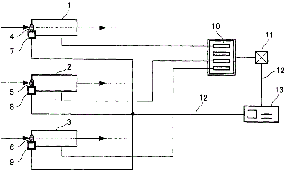
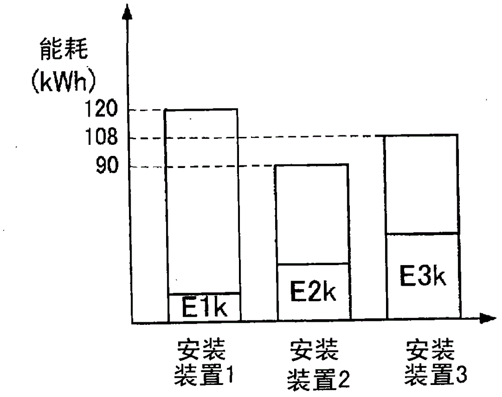
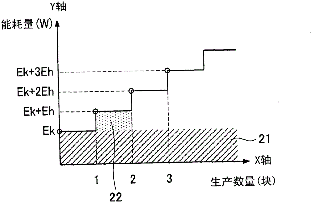
[0035] figure 1 It is a schematic diagram showing an example of the configuration of an apparatus for implementing the equipment operation state diagnosis method of the present invention. figure 2 It is a figure which exemplifies the relationship between the energy consumption of each target device of the present invention and the number of processes, image 3 It is a figure showing the relationship between the fixed energy and the proportional energy of each object device of the present invention and the number of processed objects by way of example, Figure 4 It is a figure showing an example of the power-on timing of the target device, Figure 5 is a timing chart showing an example of the operating state of the target device, Image 6 It is a graph showing an example of a change in the energy consumption per hour of the target device...


PUM


Abstract

The invention relates to an apparatus working state diagnostic method and an apparatus working state diagnostic device, the fixed energy and the proportion energy (step 2) of each object-based apparatus in an hour can be figutred out based on the total energy consumption of all of the object-based apparatuses and the manufacturing number of each object-based apparatus, and then the working states of the object-based apparatuses can be diagnosed based on the fixed energy and the proportion energy (step 3), therefore, the working states of the object-based apparatuses can be diagnosed by using a measuring instrument in a minimum degree in real time even in a device structure including a plurality of object-based apparatuses.

Description

technical field [0001] The invention relates to a method and a device for diagnosing the working state of equipment when using equipment and machinery for production and the like. Background technique [0002] In recent years, environmental issues such as global warming have become a hot topic, and it is necessary and indispensable to reduce the greenhouse gas that causes it. In addition, in Japan's Energy Conservation Law, the obligation to reduce greenhouse gas emissions per unit of activity, that is, unit consumption, is also determined. Energy increases and decreases are correctly visualized and measures are taken to reduce wasted energy. [0003] In addition, power consumption may increase due to a failure of the device or the like, so that a failure of the device can also be diagnosed based on an abnormality in power consumption. [0004] As an existing method for diagnosing equipment working conditions, there are Figure 12 Shown is the method of using the energy co...

Claims


Application Information

Patent Timeline
Patent Type & Authority Applications(China)
IPC IPC(8): G01M99/00G01R31/00
Inventor 山下英毅中裕之松田直子
Owner PANASONIC INTELLECTUAL PROPERTY MANAGEMENT CO LTD
Why Eureka
Try Eureka