Induction rotor assembly and method of manufacturing same

A component and rotor technology, applied in the field of manufacturing induction rotor components, can solve problems such as porosity

Active Publication Date: 2012-11-28
GM GLOBAL TECH OPERATIONS LLC
View PDF5 Cites 16 Cited by
  • Summary
  • Abstract
  • Description
  • Claims
  • Application Information

AI Technical Summary

Problems solved by technology

The different volumes of the conductor bars relative to

Method used


Image

  • Induction rotor assembly and method of manufacturing same
  • Induction rotor assembly and method of manufacturing same
  • Induction rotor assembly and method of manufacturing same

Examples


Embodiment Construction

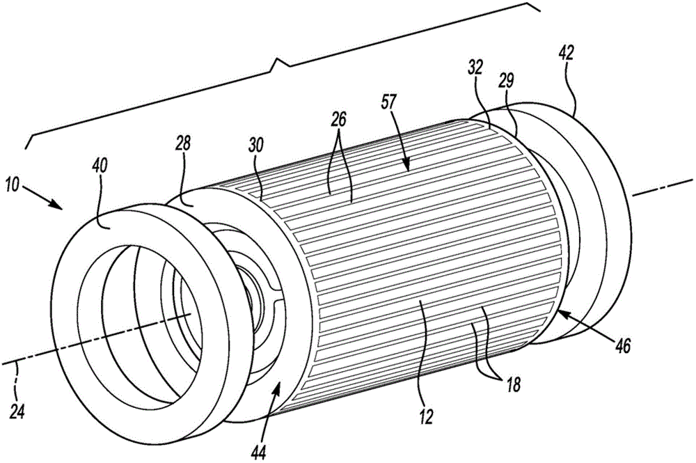
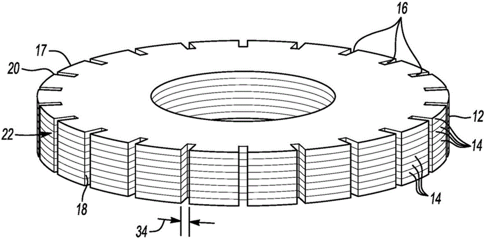
[0013] Referring to the drawings, wherein like reference numerals represent like parts throughout the several views, figure 1 The induction rotor assembly 10 is shown in an exploded view. The rotor assembly 10 includes a generally cylindrical rotor core 12 . The rotor core 12 is a lamination stack of identical sheets 14 of high magnetic steel, also referred to herein as a disc, as figure 2 , wherein some of the sheets 14 of the rotor core 12 are shown stacked to at least partially form as figure 1 The rotor core 12 is shown. Each plate 14 has grooves 16 spaced around its periphery 17 . When the plates 14 are stacked together, the grooves 16 of each plate 14 align with the grooves 16 in the adjacent plate 14 to define a perimeter 20 spaced around the outer surface 22 of the rotor core 12 and parallel to the central axis. The axial groove 18, the central axis is also the rotation axis 24 of the rotor assembly 10, such as figure 1 shown. A person skilled in the art underst...


PUM


Abstract

A method of manufacturing a rotor assembly includes placing a generally cylindrical rotor core in a die. The rotor core has axial grooves spaced about a perimeter of the rotor core. The grooves may be formed by stacked laminated disks. Material is cast around the annular rotor core in the die such that the cast material forms conductor bars that fill the grooves and first end ring portions at opposing ends of the rotor core connected with the conductor bars. Each of the first end ring portions has substantially a first axial width. The rotor core with cast conductor bars and cast first end ring portions is then removed from the die. A respective second end ring portion is welded to each of the cast first end ring portions to form end ring assemblies. Each second end ring portion has a second axial width greater than the first axial width.

Description

technical field [0001] The invention relates to a method of manufacturing an induction rotor assembly and an induction rotor assembly manufactured according to the method. Background technique [0002] An alternating current (AC) induction motor is a specific type of electric motor that uses an induced current to magnetize portions of the motor's rotor during operation of the motor. The induced current flows through conductor bars parallel to the axis of rotation of the rotor and around the circumference of the rotor core. [0003] Known methods of manufacturing induction motor rotors are time consuming and relatively expensive. A common practice is to assemble prefabricated conductor bars and shorting rings onto the lamination stack and braze the assemblies together. This method is time consuming. Another known method is to die cast the shorting rings and conductor bars together in a mold around the rotor stack. With some materials, such as copper, die casting is diffic...

Claims


Application Information

Patent Timeline
IPC IPC(8): H02K15/02H02K1/22
CPCH02K15/02H02K15/0012H02K1/22H02K17/165Y10T29/49012
Inventor R.M.克莱伯J.S.阿加皮奥
Owner GM GLOBAL TECH OPERATIONS LLC
Why Eureka
Try Eureka