
vehicle drive train

An engine and electric motor technology, applied in the field of transmission, can solve the problems of increased cost, increased structure space, complex structure, etc., and achieve the effects of reduced cost/cost, reduced fuel consumption, and reduced structure space

Inactive Publication Date: 2016-07-13
SCHAEFFLER TECH AG & CO KG
View PDF9 Cites 0 Cited by
  • Summary
  • Abstract
  • Description
  • Claims
  • Application Information

AI Technical Summary

Problems solved by technology

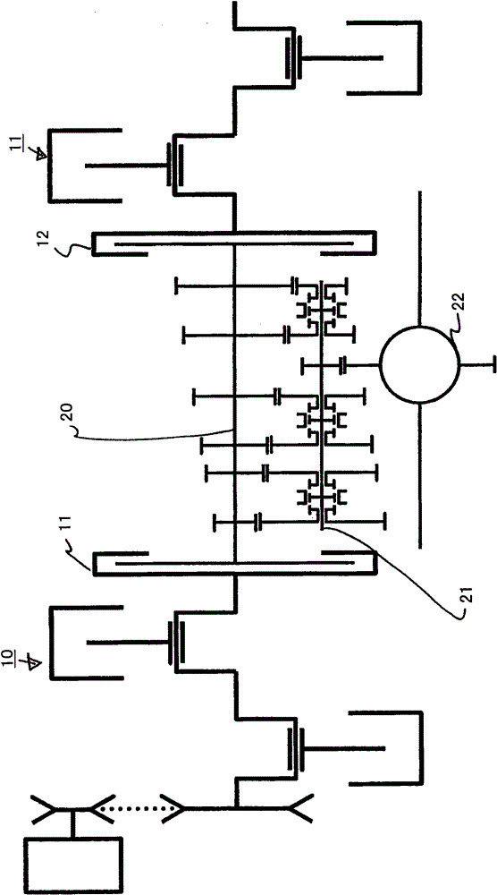
[0008] but image 3 The transmission-engine unit shown in , which has a separate crankshaft in the engine in order to save fuel and transmits the generated torque to the transmission via a connecting part, has a relatively complex structure
In combination with a double clutch, three clutches are required, which increases the outlay and the resulting costs as well as the required installation space compared to conventional systems

Method used


Image

  • vehicle drive train
  • vehicle drive train
  • vehicle drive train

Examples


Embodiment Construction

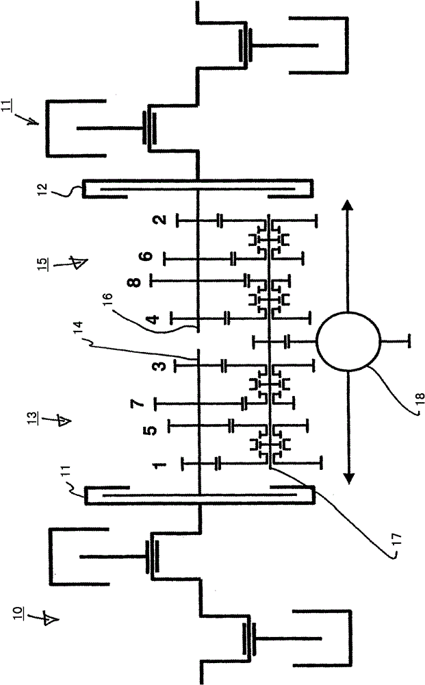
[0028] figure 1 A first embodiment of a transmission-motor arrangement with two drive units that can be operated independently of each other and a dual-clutch transmission, ie with a twin engine with a transmission, is shown in .

[0029] The transmission-engine arrangement includes a first drive unit 10 , which is designed here as a opposed engine 10 . Since such a opposed-twin engine is known per se, a detailed description of an example of the drive unit is omitted.

[0030] The transmission-motor arrangement here also includes a second drive unit 11 , which is also designed here as a opposed engine.

[0031] However, the preferred use of the two opposed twin cylinder engines is not to be understood as mandatory. Instead, other internal combustion engines or electric motors or combinations of internal combustion engines and electric motors can also be used as first drive unit 10 and / or second drive unit 11 .

[0032] The opposed-cylinder engine 10 is connectable via a cl...


PUM


Abstract

The present invention relates to a transmission-engine arrangement for saving fuel, comprising a twin engine and a transmission having two transmission inputs.

Description

technical field [0001] The invention relates to a drive train of a vehicle and a method for operating the drive train and in particular to a transmission-engine arrangement. Background technique [0002] In order to reduce the fuel consumption of the internal combustion engine, it is advantageous if the internal combustion engine can be designed for a constant load or for a relatively narrow power range, so that a corresponding optimization can be achieved. However, this is generally not transferable to known drives for vehicles. [0003] In DE3145381A1, a transmission-engine arrangement for saving fuel is disclosed, in which an internal combustion engine is divided into two or more independent partial internal combustion engines, in that the crankshaft is divided into two or more partial crankshafts, which are constructed as Engage according to the required torque. [0004] This transmission-engine arrangement for saving fuel is also given in Figure 4 In , it represents ...

Claims


Application Information

Patent Timeline
Patent Type & Authority Patents(China)
IPC IPC(8): B60K5/08F16H3/00F02D25/04B60K6/48F02B73/00F16H61/688
CPCB60K5/08B60K6/48B60K2006/4825B60K2006/4833B60Y2400/71F16H3/089Y02T10/62
Inventor O·弗里德曼
Owner SCHAEFFLER TECH AG & CO KG
Learn More