Special hydraulic machine for horizontal fan pressure shaft

A technology for hydraulic presses and fans, applied in the field of hydraulic presses, can solve the problems of misalignment, easy wear of fan shafts, low efficiency, etc., and achieve the effect of accurate force direction

Inactive Publication Date: 2012-12-05
NANTONG GAOYE HEAVY IND CO LTD
View PDF5 Cites 5 Cited by
  • Summary
  • Abstract
  • Description
  • Claims
  • Application Information

AI Technical Summary

Problems solved by technology

The traditional method uses manual beating for installation, which is prone to misalignment during installation, the fan shaft is easy to wear, and the labor intensity of the workers is high and the efficiency is low

Method used


Image

  • Special hydraulic machine for horizontal fan pressure shaft
  • Special hydraulic machine for horizontal fan pressure shaft
  • Special hydraulic machine for horizontal fan pressure shaft

Examples


Embodiment Construction

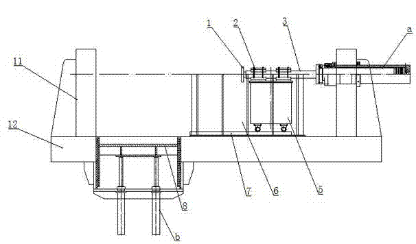
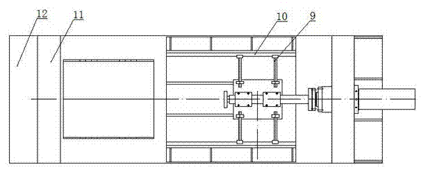
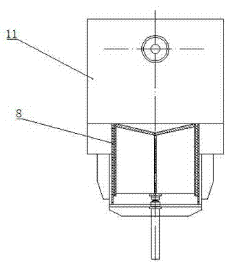
[0018] Such as figure 1 , 2 , 3, including pressing plate 1, mounting plate 2, horizontal length adjustment mechanism 3, supporting trolley 5, lateral support 6, trolley guide rail 7, fan bracket 8, adjusting screw 9, lateral limit slide rail 10, Support 11, base 12, hydraulic cylinder a, vertical hydraulic cylinder b.

[0019] The above-mentioned base 12 and the supports 11 on both sides constitute a horizontal frame, and a pressing drive mechanism that can move in the horizontal direction is installed on the support 11 on one side. In this embodiment, the pressing drive mechanism is a hydraulic cylinder a. The front end of the driving mechanism is connected with the pressing plate 1 .

[0020] A horizontal length adjustment mechanism 3 is arranged between the pressing driving mechanism and the pressing plate 1 . In this embodiment, the horizontal length adjustment mechanism 3 includes a sleeve and a screw rod built in the sleeve. The inner wall of the sleeve is threadedly...


PUM


Abstract

The invention relates to a special hydraulic machine for a horizontal fan pressure shaft. The special hydraulic machine comprises a horizontal stand, wherein the stand consists of a base and brackets arranged on two sides of the base. The special hydraulic machine is characterized in that a press driving mechanism capable of moving along the horizontal direction is arranged on the bracket on one side of the base; the front end of the press driving mechanism is connected with a pressing plate; a fan bracket is arranged at the bottom of the stand; and an upper end surface of the fan bracket is of a V-shaped groove structure. When the special hydraulic machine is in use, a fan casing is arranged on the fan bracket and the pressing plate is pushed by the press driving mechanism to move forwards to press the fan shaft into the center of the casing. A horizontal length adjusting mechanism is arranged between the press driving mechanism and the pressing plate and can adapt to casings with different thicknesses and ensure a proper pressing force. A guiding support mechanism is arranged on the horizontal length adjusting mechanism, and thus the horizontal forward movement of the pressing plate is ensured, the stress direction is accurate and the bias press is avoided.

Description

technical field [0001] The invention relates to a hydraulic machine, in particular to a special hydraulic machine for the finale of a horizontal fan. Background technique [0002] In the process of manufacturing the fan, it is necessary to press the fan shaft into the center of the housing to install the fan shaft. The traditional method uses manual beating for installation, which is prone to misalignment during installation, the fan shaft is easy to wear, and the labor intensity of the workers is high and the efficiency is low. Contents of the invention [0003] The technical problem to be solved by the present invention is to provide a special hydraulic press for the finale of a horizontal fan with high processing precision and wide application range. [0004] In order to solve the above-mentioned technical problems, the technical solution of the present invention is: a special hydraulic press for the finale of a horizontal fan, including a horizontal frame, the frame i...

Claims


Application Information

Patent Timeline
Patent Type & Authority Applications(China)
IPC IPC(8): B23P19/027
Inventor 邵正国赵兴华陆新建邵志强仇云云
Owner NANTONG GAOYE HEAVY IND CO LTD
Why Eureka
Try Eureka