
A powertrain hydraulic mount with throttle disc

A powertrain, hydraulic mount technology, applied in power plant, jet propulsion, internal combustion propulsion, etc., can solve the problems of insufficiency, limited dynamic hardening frequency, unfavorable vibration isolation, etc., to improve the vibration isolation performance, prolong the Effect of high frequency dynamic hardening frequency

Active Publication Date: 2016-05-04
NINGBO TUOPU GROUP CO LTD
View PDF6 Cites 0 Cited by
  • Summary
  • Abstract
  • Description
  • Claims
  • Application Information

AI Technical Summary

Problems solved by technology

Conventional powertrain hydraulic mounts have large damping and high stiffness characteristics under low-frequency and large-amplitude excitation, which is conducive to attenuating road vibration, thereby reducing vibration and noise in the vehicle; while under high-frequency and small-amplitude excitation, dynamic hardening is prone to occur At this time, the dynamic stiffness is high, which is not conducive to vibration isolation. The vibration generated by the powertrain is very easy to be transmitted to the vehicle through the hydraulic mount, which is not conducive to the improvement of the NVH performance of the vehicle. Therefore, how to eliminate or reduce the vibration of the powertrain hydraulic mount The phenomenon of dynamic hardening has extremely important engineering significance for improving the vibration isolation performance of the powertrain mounting system
[0003] At present, the existing hydraulic mount generally reduces the dynamic hardening phenomenon of the hydraulic mount by installing a decoupling membrane inside it, and improves the vibration isolation performance of the powertrain mount system. The dynamic hardening frequency is very limited, generally between 100-150Hz, and for high-power, high-speed powertrains, the dynamic hardening frequency is required to be between 200-300Hz, so the current existing hydraulic mounts cannot meet the requirements. Requirements for this type of powertrain mount system

Method used


Image

  • A powertrain hydraulic mount with throttle disc

Examples


Embodiment Construction

[0019] The present invention will be described in further detail below in conjunction with the accompanying drawings and specific embodiments:

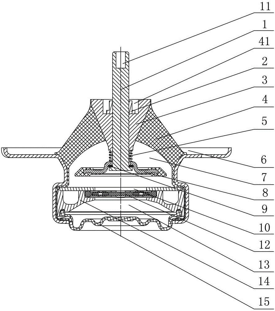
[0020] like figure 1 As shown, a powertrain hydraulic mount with a throttle disc includes a connecting bracket 6 , an elastic main spring 4 arranged on the connecting bracket 6 , an upper liquid chamber 7 and a lower liquid chamber 13 . The elastic main spring 4 is provided with an inner core 3; the upper liquid chamber 7 and the lower liquid chamber 13 are separated by the flow channel assembly, and a throttle disc 8 is arranged in the upper liquid chamber 7; the throttle disc 8 and the inner core 3 Connected by bolts 1 , a spring 5 is arranged between the throttle disc 8 and the inner core 3 .

[0021] The lower end of the bolt 1 is provided with an inner hexagonal screw hole 11 , and the inner core 3 is provided with a threaded hole matched with the bolt 1 .

[0022] The upper end surface of the inner core 3 is provided with a gr...


PUM


Abstract

The invention discloses a hydraulic power train mount with a throttle disc. The hydraulic power train mount comprises a connecting support, an elastic mainspring, an upper liquid chamber and a lower liquid chamber, wherein the elastic mainspring, the upper liquid chamber and the lower liquid chamber are mounted on the connecting support. An inner core is arranged on the elastic mainspring, and the upper liquid chamber and the lower liquid chamber are partitioned via a passageway assembly. The hydraulic power train mount is characterized in that the throttle disc is arranged in the upper liquid chamber and connected with the inner core via bolt, and a spring is arranged between the throttle disc and the inner core. The hydraulic power train mount with the throttle disc has the advantage that liquid column resonance phenomenon therein can be postponed, and high dynamically hardening frequency can be effectively prolonged, so that vibration isolation performance of the hydraulic power train mount can be improved, and NVH (noise vibration and harshness) and comfort of a whole car are facilitated.

Description

technical field [0001] The invention relates to a power assembly hydraulic mount, in particular to a power assembly hydraulic mount with a throttle disc. Background technique [0002] Due to its good vibration damping and isolation performance, hydraulic mounts are more and more widely used in automotive powertrain mount systems. The conventional powertrain hydraulic mount has the characteristics of large damping and high stiffness under low-frequency and large-amplitude excitation, which is conducive to damping road vibration, thereby reducing vibration and noise in the vehicle; however, under high-frequency small-amplitude excitation, dynamic hardening is prone to occur. , At this time, the dynamic stiffness is high, which is not conducive to vibration isolation. The vibration generated by the powertrain is easily transmitted to the vehicle through the hydraulic mount, which is not conducive to the improvement of the NVH performance of the vehicle. Therefore, how to elimin...

Claims


Application Information

Patent Timeline
Patent Type & Authority Patents(China)
IPC IPC(8): B60K5/12
Inventor 段小成叶必军俞超
Owner NINGBO TUOPU GROUP CO LTD
Learn More