Support system for a forklift power train

a support system and forklift technology, applied in the direction of electric propulsion mounting, jet propulsion mounting, transportation and packaging, etc., can solve the problems of fan interference, damage to intake and exhaust pipes, and breakage of universal joints, so as to reduce vibration transmission to the body side, reduce vibration transmission, and reinforce the effect of vibration isolation

Inactive Publication Date: 2007-03-06
KOMATSU LTD
View PDF19 Cites 13 Cited by
  • Summary
  • Abstract
  • Description
  • Claims
  • Application Information

AI Technical Summary

Benefits of technology

[0021]With the configuration described above, wherein with a three-point mount system adopted as shown in FIGS. 1 to 3, by disposing the front side support at one location in the vicinity of the roll axis, where an amplitude of the roll vibration of the power train is small, vibration transmission to a body side can be reduced as compared with that of the four-point mount system.
[0022]Further, since the forklift is provided with the counterweight in the rear part of the body thereof, the forklift has its inherent characteristics that the closer a position is to the counterweight, the less vibration transmission to the position tends to be, thereby reinforcing the vibration isolation effect of the three-point mount system with a synergistic effect.
[0023]More specifically, with the four-point mount system, because supports at two points, the right and left sides, respectively, on the rear side, are disposed close to the counterweight, these supports can obtain the vibration isolation effect to a degree, however, supports at two points, the right and left sides, respectively, on the front side, are disposed farther from the counterweight, so that vibration tends to be transmitted to the body side therethrough. In contrast, with the three-point mount system, by bringing the front side support location at one point closer to the roll axis of the power train as described above, vibration transmission to the body side can be significantly reduced, so that the forklift can have obtained an advantageous effects over an effect due to simply changing from the four-point mount system to the three-point mount system.
[0024]Further, as shown in FIG. 3, with the three-point mount system, the front side support is located in the vicinity of the inertial main axis (the roll axis X—X), so that the roll vibration of the power train is very small in amplitude, and even if rigidity of the support is raised, there does not occur deterioration in vibration. Accordingly, this makes it possible to use a reasonably harder vibration isolation member at the support. Furthermore, as for the supports at two points on the rear side, as well, the rigidity of the supports can be raised (the vibration isolation members can be rendered harder) as compared with the case of the four-point mount system for the following reason.
[0025]More specifically, in FIG. 9(a), assuming that a supporting capacity of one support is K, the sum total of support rigidities (moment) against the roll vibration of a power train in the case of the four-point mount system is represented by K×L×4.
[0026]Then, in FIG. 9(b), assuming that a supporting capacity of one support is K′, the sum total of support rigidities (moment) against the roll vibration of a power train in the case of the three-point mount system is represented by K′×L×2.

Problems solved by technology

In such a state, however, rocking (swaying back-and-forth and from side-to-side in such a case as when the vehicle is suddenly accelerated, decelerated or turned) of the power train, other than the roll vibration, increases, causing problems such as breakage of the universal joint, interference between a fan and a shroud, damage to intake and exhaust pipes, generation of abnormal sounds, and so forth.

Method used


Image

  • Support system for a forklift power train
  • Support system for a forklift power train
  • Support system for a forklift power train

Examples


first embodiment

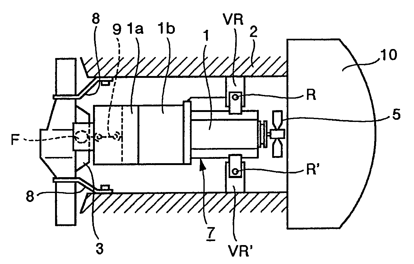
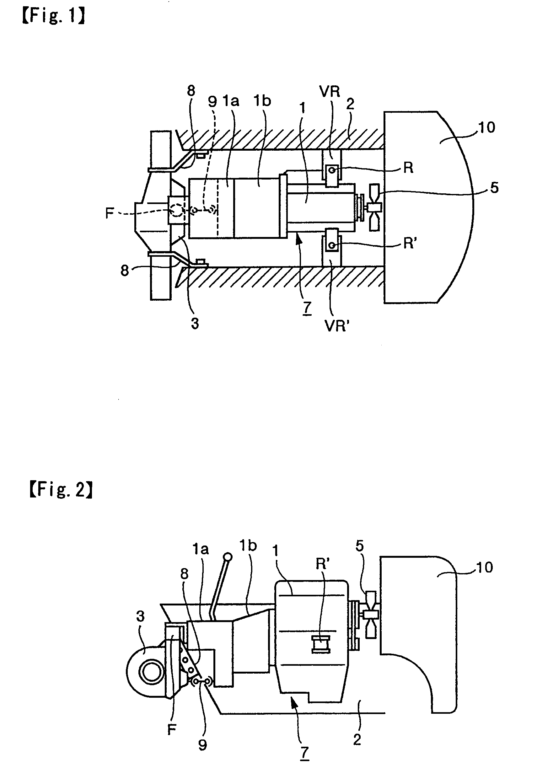
[0097]FIG. 1 is the plan view showing the first embodiment of the invention, and FIG. 2 is the side view of the first embodiment shown in FIG. 1.

[0098]With the forklift provided with the counterweight 10 in the rear part of the body frame 2, the differential gear case 3 is coupled to the front side of the body frame 2 through the axle support 8. Further, the power train 7 comprises an engine 1; a power transmission device 1b including a clutch or torque converter, and so forth, and a transmission case 1a, provided in that order from the rear side of the body frame 2, wherein the output shaft of the transmission case 1a is coupled with the differential gear case 3 side by the universal joint 9. The power train 7 is supported by the frame brackets VR′, VR, at the two locations on the rear side of the body frame 2, by the rear side support members R′, R, respectively, and on the front side of the body frame 2, the front side support member F is disposed at the one location positioned b...

second embodiment

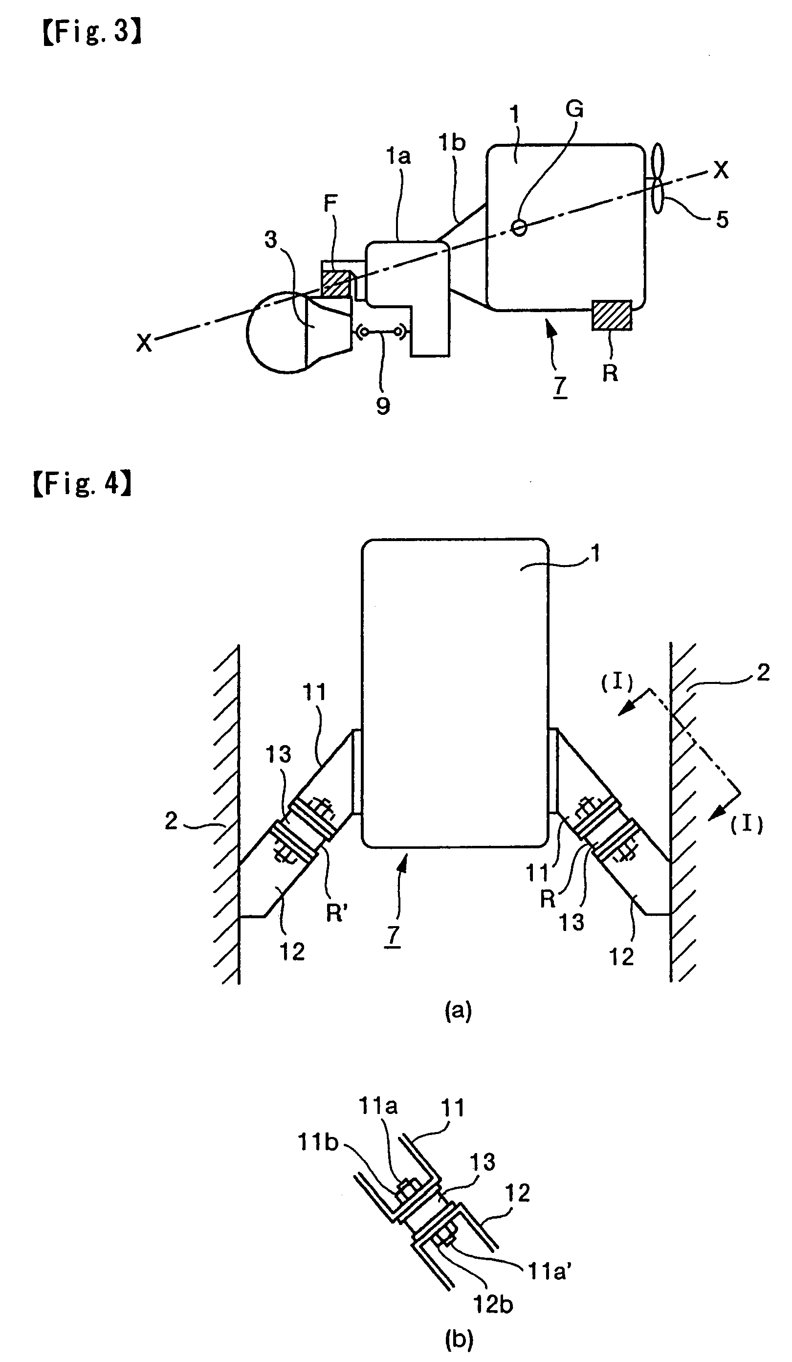
[0114]FIG. 3 is the side view of the support system for the power train 7, in the V-shaped mount structure, according to the second embodiment of the invention, FIG. 4(a) is the front view of the V-shaped mount structure, and FIG. 4 (b) is the view of the support of the V-shaped mount structure, as seen from (I)—(I) in FIG. 4(a).

[0115]With the front side support member F of the power train 7 being disposed in the vicinity of the roll axis X—X, the rear side support members R′, R, on the right and left sides of the frame side mount brackets 12, 12, respectively, are disposed such that the installation faces thereof are substantially in the form of the letter V, thereby adopting the so-called V-shaped mount structure. That is, the vibration isolation members 13, 13 are sandwiched between the engine side mount brackets 11, 11 and the frame side mount brackets 12, 12, respectively, and fixed thereto, respectively, by the support member side installation bolts 11a, 11a′ and the nuts 11b,...

third embodiment

[0118]FIG. 7 is the plan view of the third embodiment of the invention, and FIG. 8 is the side view of the third embodiment shown in FIG. 7.

[0119]With the forklift provided with the counterweight 60 in the rear part of the body frame 52, the differential gear case 53 is attached to the front side of the body frame 52 by the axle support 58. The power train 57 comprises the engine 51, the power transmission device 51b including the clutch or torque converter, and so forth, and the transmission case 51a, provided in that order from the rear side of the body frame 52, wherein the output shaft in the transmission case 51a is coupled with the differential gear case 53 side through the intermediary of the universal joint 59. Further, the power train 57 is supported by the frame brackets 50VR′, 50VR, through the rear side support members 50R′, 50R, respectively, on the rear side thereof while on the front side thereof, the front side support member 50F is provided at one location and on th...


PUM


Abstract

There is provided a support system for a forklift power train, having little vibration transmission to a body frame, but capable of effectively suppressing movement of the power train against even a quick movement of a vehicle occurred in such a case as when the vehicle is accelerated, decelerated, turned or the like, and simpler in construction for assembling workability.
  • In the support structure for a power train of a forklift having a counterweight in the rear part of the body frame, while a front side support is provided at one location positioned at a differential gear case or a frame side cross member and in the vicinity of the roll axis of the power train, a rear side support is provided at two locations, on the right and left sides of the roll axis of the power train, respectively, in the rear part of the body frame, thereby supporting the power train at three locations in all.

Description

FIELD OF THE INVENTION[0001]The invention relates to a support system for a forklift power train including an engine and a transmission.BACKGROUND OF THE INVENTION[0002]With a conventional support structure for a forklift power train, in the case of a forklift provided with a counterweight 110 in the rear part of a body frame 102 as shown in FIGS. 10, and 11, a differential gear case 103 is attached to the front side of the body frame 102 through the intermediary of an axle support 108. Further, there is formed a power train 107 comprising an engine 101, a power transmission device 101b, such as a clutch or torque converter, and so forth, and a transmission case 101a, provided in that order from the rear side of the body frame 102, wherein an output shaft of the transmission case 101a is coupled with the differential gear case 103 side of the body frame 102 through the intermediary of an universal joint 109. Further, on the front side of the body frame 102, the power train 107 is su...

Claims


Application Information

Patent Timeline
Patent Type & Authority Patents(United States)
IPC IPC(8): B66F9/08B60K5/02B60K5/12B60K17/06B60K17/16B66F9/075F16F1/54
CPCB60K5/1208B60K5/1241F16F1/54B66F9/07595B66F9/07572
Inventor AOYAMA, YOUICHISHINOHARA, SHIGEO
Owner KOMATSU LTD
Why Eureka
Try Eureka