Subframe structure

a subframe and vehicle technology, applied in vehicle components, jet propulsion mounting, propulsion parts, etc., can solve the problem of difficult vibration isolation device to extend the vibration shielding region

Active Publication Date: 2017-04-18
HONDA MOTOR CO LTD
View PDF10 Cites 12 Cited by
  • Summary
  • Abstract
  • Description
  • Claims
  • Application Information

AI Technical Summary

Benefits of technology

[0010]According to this configuration, even if the subframe is rigidly attached to the body frame, the load input point (IP) is arranged to be positioned within a region (G) surrounded by multiple support points (SP) in planar view. Due to this arrangement, excessive vibrations in the longitude direction of the vehicle that are input from the load input point (IP), and excessive vibrations in the lateral direction of the vehicle, are absorbed at the multiple support points (SP). Accordingly, excessive vibrations in the longitude direction of the vehicle and excessive vibrations in the lateral direction of the vehicle are kept from being added to the vibrations in the vertical direction of the vehicle input from the load input point IP. As a result, the vibration-shielding region by the vibration-isolation device can be extended, and vibration isolation effects can be improved over the related art even further.
[0013]According to this configuration, the steering gearbox can be suitably disposed using the accommodation recess formed in the attachment bracket. As a result, the scant space at the front of the vehicle where the vehicular power plant is accommodated can be used efficiently, and freedom of layout within the space can be improved.
[0015]According to this configuration, providing attachment portions on both ends of the lateral member in the lateral direction of the vehicle secures space to attach suspension arms.

Problems solved by technology

On the other hand, in a case where the load input point (IP) is situated outside of the region (G) surrounded by the support points (SP), excessive vibrations in the longitudinal direction of the vehicle and excessive vibrations in the lateral direction of the vehicle are added to the vibrations in the vertical direction of the vehicle input from the load input point (IP), so extending the vibration-shielding region by the vibration-isolation device becomes difficult.

Method used


Image

  • Subframe structure
  • Subframe structure
  • Subframe structure

Examples


Embodiment Construction

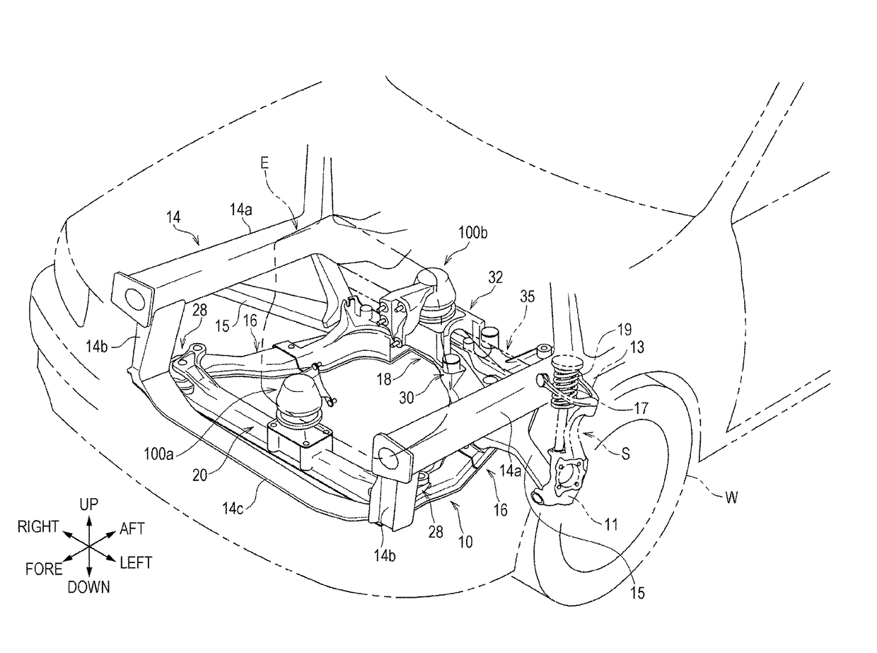
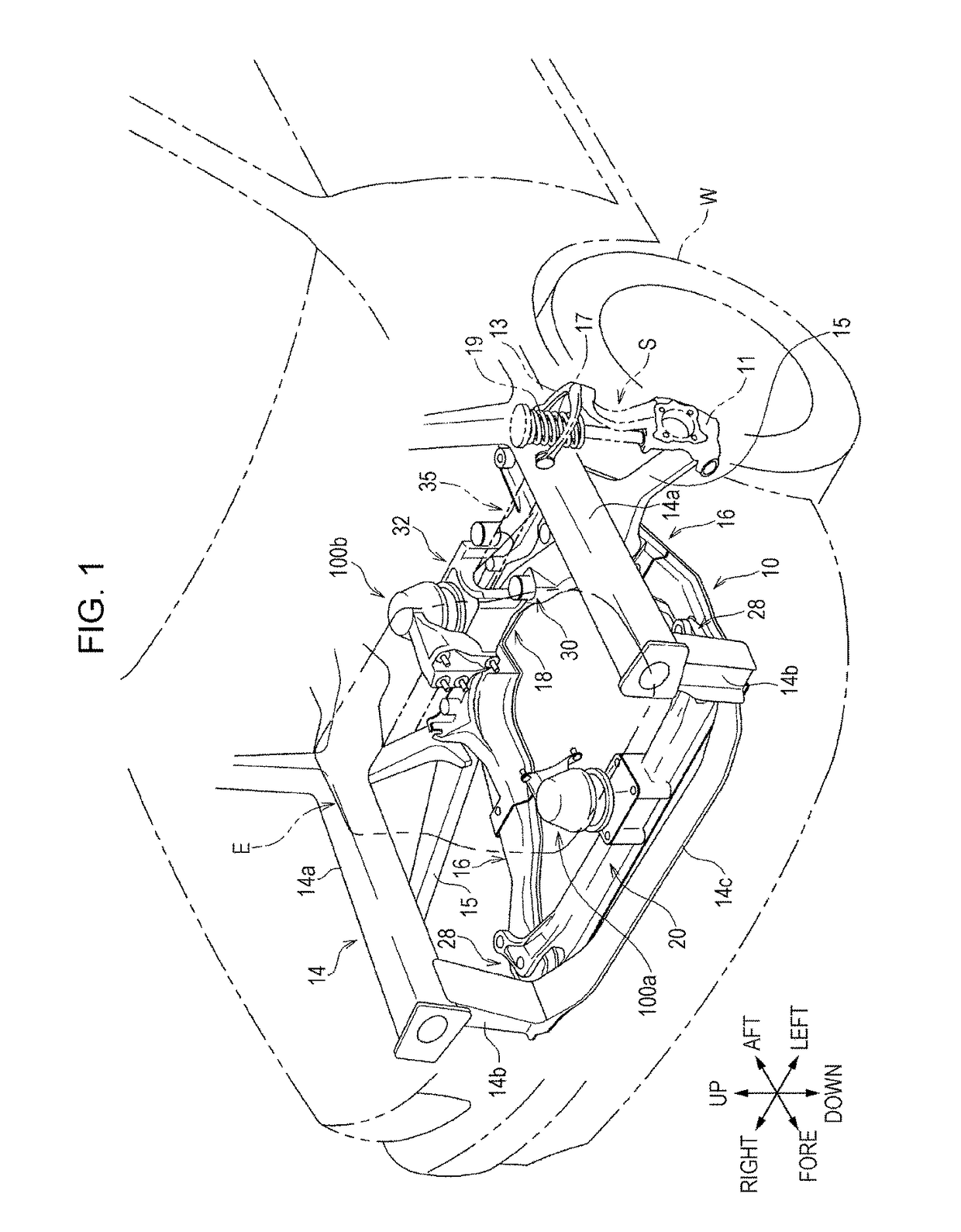
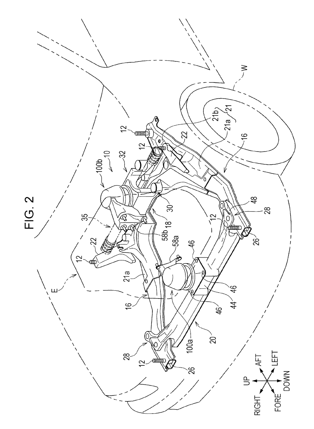
[0031]An embodiment of the present disclosure will be described next with reference to the drawings. FIG. 1 is a cutaway perspective view illustrating a state where a subframe structure according to an embodiment of the present disclosure has been disposed in the front portion of an automobile. FIG. 2 is a cutaway perspective view of the subframe structure, where right and left front side frames and other components have been removed from the state illustrated in FIG. 1. FIG. 3 is a perspective view of the subframe structure. FIG. 4 is a disassembled perspective view of the subframe structure illustrated in FIG. 3. FIG. 5A is a planar view of the subframe structure illustrated in FIG. 3 and FIG. 5B is a planar schematic view illustrating the positional relation between a load input point IP and four support points SP. FIG. 6 is a side view of the subframe structure illustrated in FIG. 3. Note that the “fore”, “aft”, “up”, and “down” indicated by the arrows in the diagrams represent ...


PUM


Abstract

A subframe structure includes an attachment bracket that is disposed between the second vibration-isolation device and rear cross member and that attach the second vibration-isolation device to the rear cross member, and four elastic bushings that floatably support the attachment bracket as to the rear cross member at four support points. A load input point where a load is input from an engine to the second vibration-isolation device is positioned within a region surrounded by the four support points in planar view.

Description

CROSS REFERENCES TO RELATED APPLICATIONS[0001]The present application claims priority under 35 U.S.C. §119 to Japanese Patent Application No. 2014-232477, filed Nov. 17, 2014, entitled “Subframe Structure.” The contents of this application are incorporated herein by reference in their entirety.BACKGROUND[0002]1. Field[0003]The present disclosure relates to a subframe structure of a vehicle.[0004]2. Description of the Related Art[0005]Vehicles such as automobiles and the like are provided with a subframe that is fixed to front side frames serving as a body frame. Suspension components such as suspension arms, stabilizers, and so forth, are attached to the side frames for example, and the subframe also supports the power plant for the vehicle, such as an engine and / or electric motor or the like, via a vibration-isolation device.[0006]For example, Japanese Unexamined Patent Application Publication No. 2000-238545 discloses a rubber vibration-absorbing elastic member 1 that absorbs vibr...

Claims


Application Information

Patent Timeline
Patent Type & Authority Patents(United States)
IPC IPC(8): B60K5/12B62D21/11
CPCB62D21/11B60K5/12B60K5/1216
Inventor HIRANO, MASATAKAMIYAHARA, TETSUYA
Owner HONDA MOTOR CO LTD
Why Eureka
Try Eureka