Array antenna apparatus and radar apparatus

Inactive Publication Date: 2011-03-17
DENSO CORP
View PDF1 Cites 40 Cited by
  • Summary
  • Abstract
  • Description
  • Claims
  • Application Information

AI Technical Summary

Benefits of technology

[0013]The present invention has been made in light of the circumstances described above, and has as its object to provide an array antenna apparatus which is able to broaden

Problems solved by technology

Therefore, there is a concern that a target detection error may be caused if the direction of the second grating lobe on the grating suppressed side is included in the visible region.
However, it is physica

Method used


Image

  • Array antenna apparatus and radar apparatus
  • Array antenna apparatus and radar apparatus
  • Array antenna apparatus and radar apparatus

Examples


Embodiment Construction

and the directivity of the reception array antenna, according to the embodiment;

[0023]FIG. 8 is a block diagram illustrating a general configuration of a radar apparatus, according to a modification of the embodiment;

[0024]FIG. 9 is a block diagram illustrating a general configuration of a radar apparatus, according to another modification of the embodiment; and

[0025]FIG. 10 is a block diagram illustrating a general configuration of a radar apparatus, according to still another modification of the embodiment.

DETAILED DESCRIPTION OF THE PREFERRED EMBODIMENTS

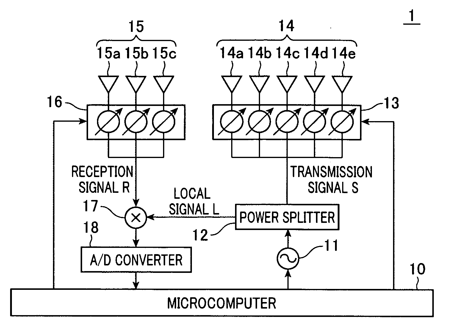
[0026]With reference to FIGS. 1 to 7, hereinafter will be described an embodiment of a radar apparatus that includes an array antenna apparatus. FIG. 1 is a block diagram illustrating a general configuration of a radar apparatus 1 that includes an array antenna apparatus according to the present embodiment. Referring to FIG. 1, the configuration and functions of the radar apparatus 1 are described first.

[0027]As shown in FIG. 1, t...


PUM


Abstract

An array antenna apparatus includes a transmission-array-antenna including transmission-antenna-elements, a transmission-side directivity control unit controlling a directivity of the transmission-array-antenna by controlling phases of at least part of the transmission-antenna-elements, a reception-array-antenna including reception-antenna-elements, and a reception-side directivity control unit controlling a directivity of the reception-array-antenna by controlling phases of the reception-antenna-elements. The array antenna apparatus has a composite transmission/reception directivity, in which the direction of a grating lobe of one of the transmission-array-antenna and the reception-array-antenna agrees with the direction of a null point or part of side lobes of the other of the transmission-array-antenna and the reception-array-antenna, and the direction of a grating lobe of the other of the transmission-array-antenna and the reception-array-antenna agrees with the direction of a null point or part of side lobes of the one of the transmission-array-antenna and the reception-array-antenna, and scans in a scanning range with the composite transmission/reception directivity.

Description

CROSS-REFERENCE TO RELATED APPLICATION[0001]This application is based on and claims the benefit of priority from earlier Japanese Patent Application No. 2009-215751 filed Sep. 17, 2009, the description of which is incorporated herein by reference.BACKGROUND OF THE INVENTION[0002]1. Technical Field of the Invention[0003]The present invention relates to an array antenna apparatus which can suppress grating lobes and to a radar apparatus that detects a target located within a scanning range of a main lobe by using the array antenna apparatus.[0004]2. Related Art[0005]The technique for providing such array antenna apparatus and radar apparatus is known as disclosed, for example, in the patent document JP-B-4147447. In the technique disclosed in the patent document JP-B-4147447, a radar apparatus includes an array antenna apparatus which is configured by a transmission array antenna having a plurality of antenna elements, a transmission processing unit connected to the transmission array...

Claims


Application Information

Patent Timeline
IPC IPC(8): H01Q3/00G01S13/04
CPCG01S7/2813H01Q3/40H01Q3/30H01Q3/24
Inventor KONDOU, ASAHI
Owner DENSO CORP
Why Eureka
Try Eureka