

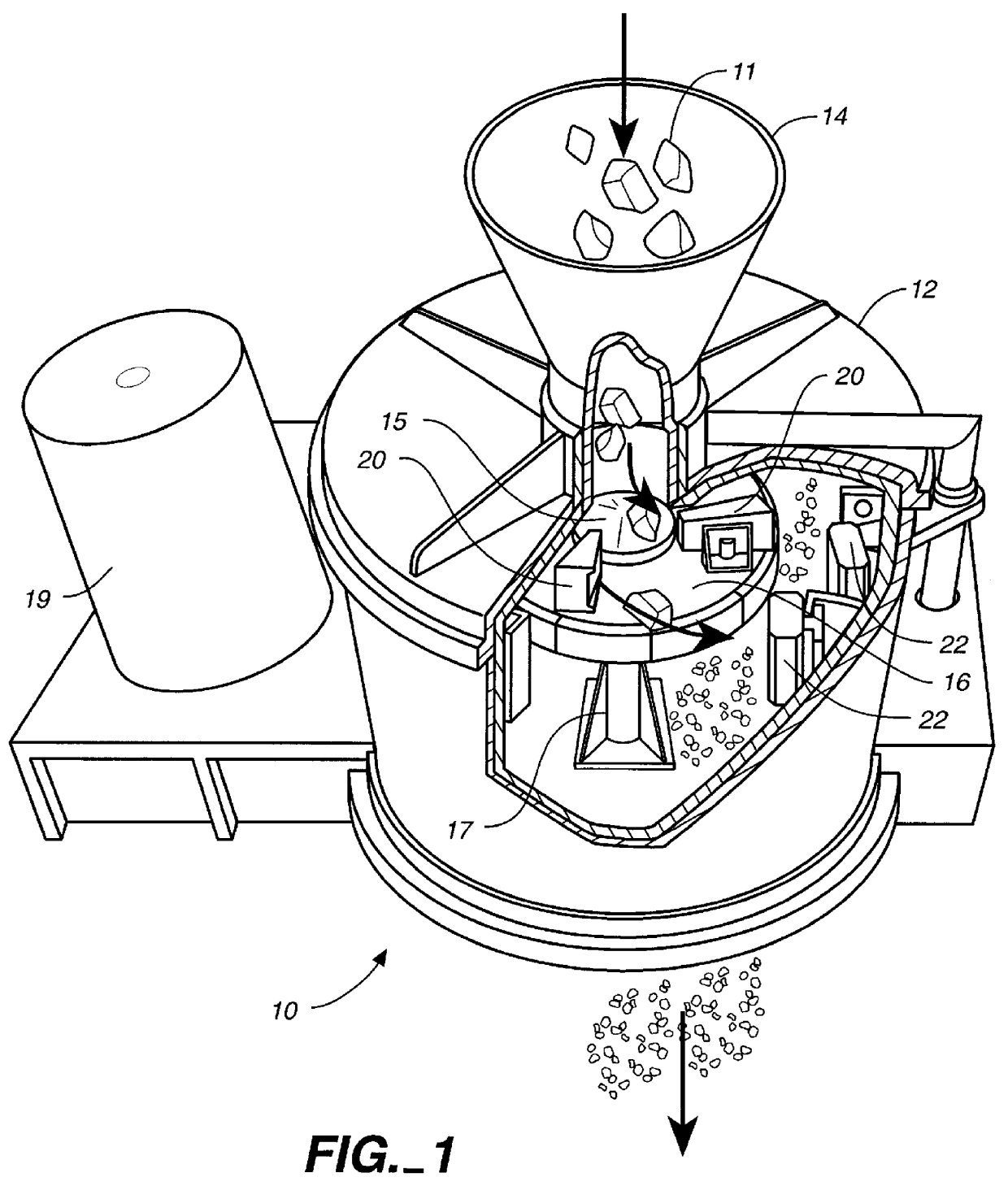
Wear resistant, high impact, iron alloy member and method of making the same
a technology of iron alloys and high impact, which is applied in the field of high impact iron alloy members, can solve the problems of alloys still subject to significant wear and abrasion, downtime and maintenance, and the greatest abrasion or wear, and achieve the effect of high impact and improved wear resistan
- Summary
- Abstract
- Description
- Claims
- Application Information
AI Technical Summary
Benefits of technology
Problems solved by technology
Method used
Image

Examples
second embodiment
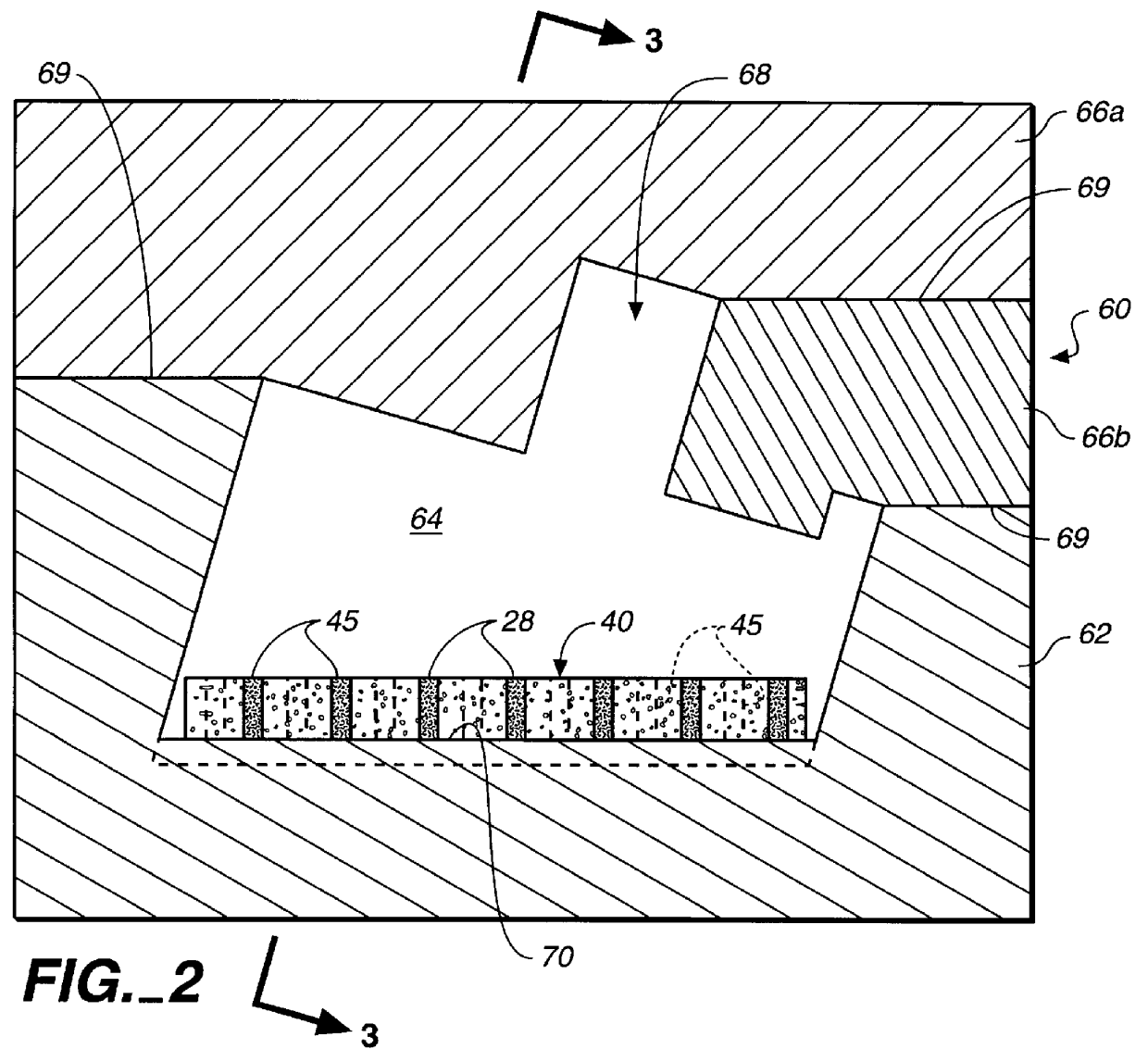
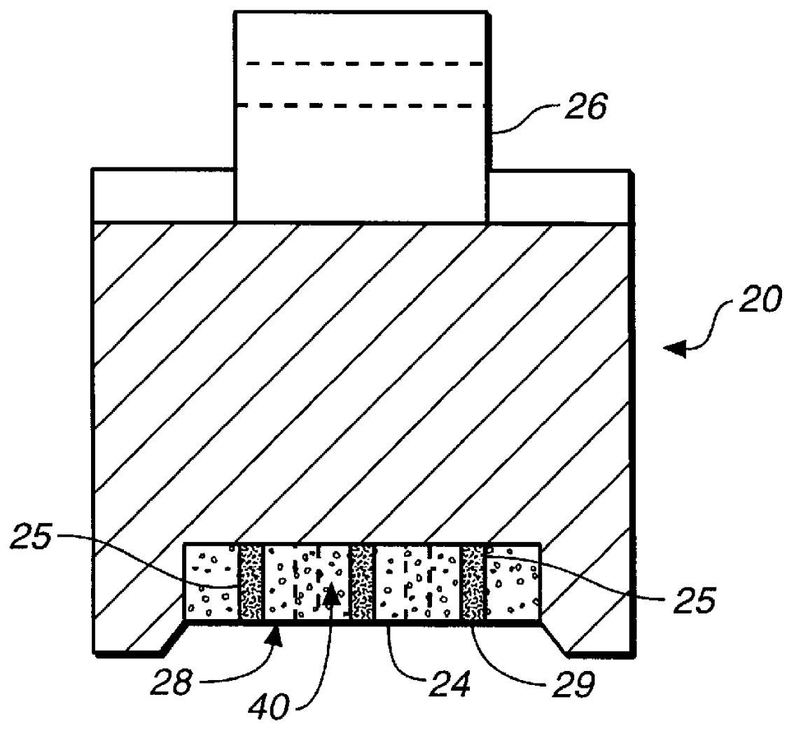
the molding insert in accordance with the present invention is shown in FIGS. 5a and 5b. The molding insert 40 is comprised of a wafer-like, porous ceramic filter material having four side surfaces 42, a top surface 41, and a bottom surface 43. Insert 40 further contains a plurality of bores 45 formed for receipt and containment of carbide granules 29. Preferably, bores 45 extend through insert 40 and are distributed relatively evenly throughout the area of the insert to form a relatively uniform pattern.
Of particular advantage, ceramic member insert 40 is also highly porous and capable of withstanding the high temperature of the molten iron, while allowing the flow of molten iron within the insert to bores 45 holding the carbide granules. Ceramic filters are widely used in the metal casting industry to mechanically remove slag from molten metals so they readily permit flow of the metal through the ceramic wafer without dissolving. Ceramic insert 40 is preferably a porous zirconia c...
examples
Impellers constructed as shown in FIGS. 2 and 3 have been cast using the method of the present invention with the following constituents:
These impellers have been used in rock crushers and a significant increase (50 to 150%) in the service life of the impellers was achieved.
PUM
| Property | Measurement | Unit |
|---|---|---|
| temperature | aaaaa | aaaaa |
| temperature | aaaaa | aaaaa |
| temperature | aaaaa | aaaaa |
Abstract
Description
Claims
Application Information