Anti-vibration device for loom

An anti-vibration device and loom technology, which is applied to looms, textiles, textiles, and papermaking, can solve the problem of not effectively utilizing the vibration energy of looms, and achieve the effect of preventing impact

Inactive Publication Date: 2012-12-05
TOYOTA IND CORP
View PDF6 Cites 5 Cited by
  • Summary
  • Abstract
  • Description
  • Claims
  • Application Information

AI Technical Summary

Problems solved by technology

However, the anti-vibration technology of the loom, which maintains the function of the loom and prevents the impact on the surrounding environment, adopts a form in which all vibration energy generated by the loom is discarded, and the vibration energy of the loom is not effectively utilized.

Method used


Image

  • Anti-vibration device for loom
  • Anti-vibration device for loom
  • Anti-vibration device for loom

Examples


no. 1 Embodiment approach )

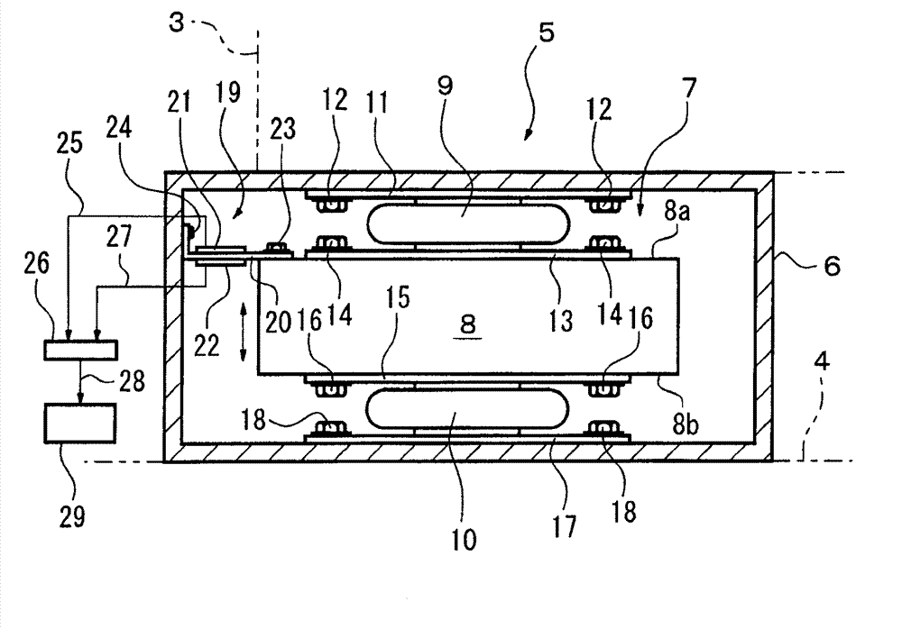
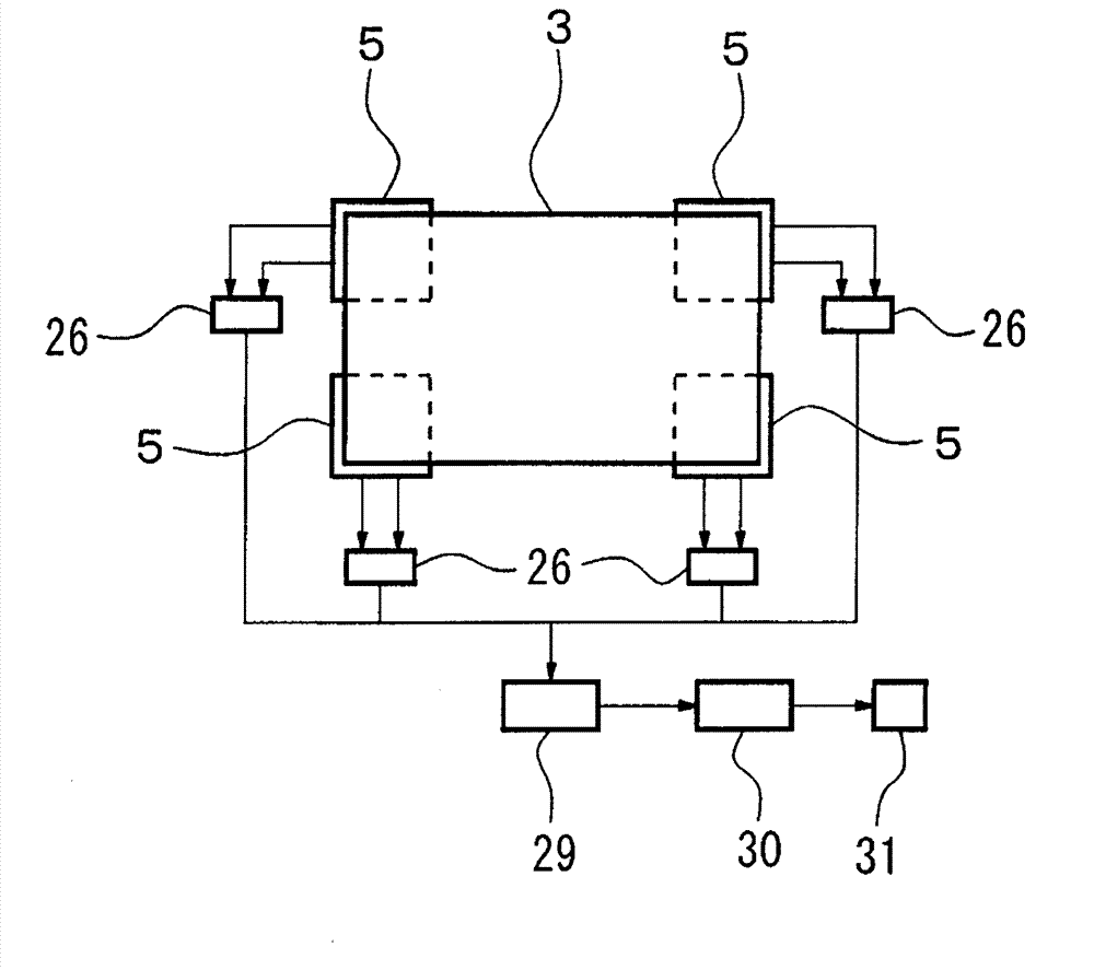
[0018] based on Figure 1 ~ Figure 3 The first embodiment will be described. exist figure 1 Among them, the loom 3 provided with the warp shedding device 1 and the reed 2 as the main source of vibration is placed on the anti-vibration stand 5 as the anti-vibration device installed on the ground 4 . The anti-vibration mounts 5 are arranged at four places, and support the frame of the loom 3 at four corners. In order to stably support the loom 3, it is necessary to arrange the anti-vibration mounts 5 in at least three places, and if necessary, the anti-vibration mounts 5 may be provided in four or more places. In addition, the anti-vibration stand 5 is fixed to the loom 3 with bolts not shown.

[0019] exist figure 2 , the details of the anti-vibration mount 5 will be described. in addition, figure 2 It is a figure showing one of the anti-vibration mounts 5 installed at four locations, and the structure is the same as that of the anti-vibration mounts installed at other ...

no. 2 Embodiment approach )

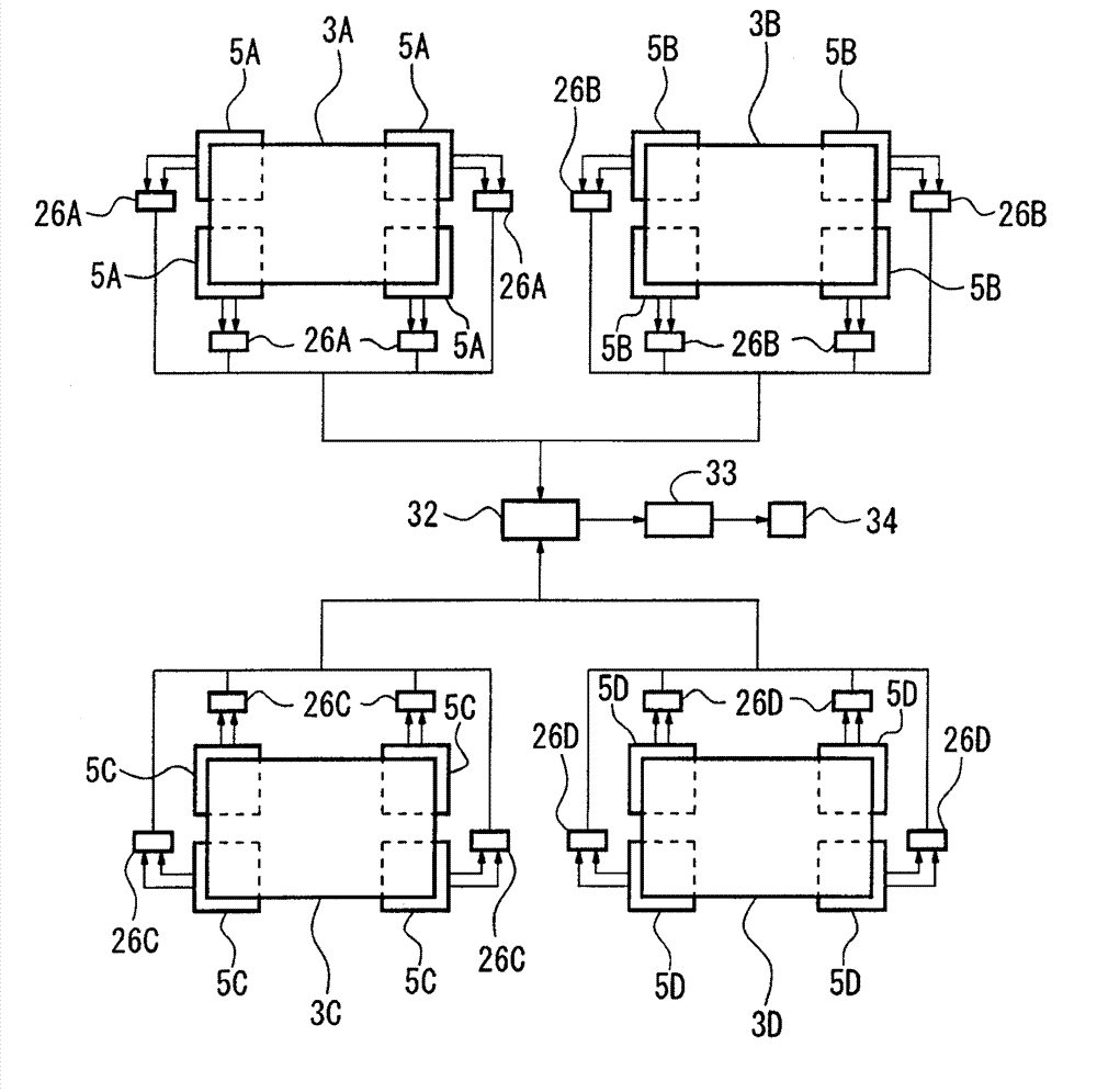
[0032] Figure 4 The second embodiment shows the power utilization form in a weaving factory in which many looms are installed, and the same reference numerals are assigned to the same structures as those in the first embodiment, and detailed description thereof will be omitted.

[0033] Figure 4It shows the power utilization form of four looms 3A, 3B, 3C, and 3D among many looms installed in a weaving factory. Each of the looms 3A to 3D is placed on four anti-vibration stands 5A to 5D installed on the ground, respectively. The anti-vibration mounts 5A to 5D have the same structure as the anti-vibration mount 5 shown in the first embodiment, and each includes figure 2 The vibration absorbing device 7 and the vibration generating mechanism 19 are shown.

[0034] The respective vibration power generating mechanisms 19 arranged on the anti-vibration mounts 5A to 5D are electrically connected to a common storage battery 32 via rectifiers 26A to 26D, respectively. The storage...


PUM


Abstract

The invention provides an anti-vibration device for a loom, by which the vibration energy generated by the operation of the loom is absorbed and the absorbed vibration energy is effectively utilized. An anti-vibration frame of a load loom consists of a housing and a vibration absorbing device. The vibration absorbing device consists of a weight arranged in the housing and vibrating freely, and a first air spring and a second air spring elastically clamping the weight. The weight vibrates with a natural frequency identical with the frequency of the loom by the vibration of the loom, and the vibration of the loom is absorbed by a reaction force of the weight. A vibration electric generator arranged between the weight and the housing comprises a piezoelectric element. The piezoelectric element is deformed repeatedly by the vibration of the weight and generates an electromotive force. In this way, the vibration of the loom and the propagation of the vibration to outside are suppressed, preventing the influence on surroundings, and the absorbed vibration energy can be effectively utilized by using the electric power obtained by the vibration of the loom for the loom or the electric equipment in the weaving factory.

Description

technical field [0001] The present invention relates to an anti-vibration device for absorbing vibration of a loom. Background technique [0002] When the loom is operated, severe vibrations are generated by the high-speed reciprocating motion of the heald frame and the reed accompanying the weaving motion. The loom is usually firmly fixed to the ground with anchor bolts, etc., and countermeasures are taken so that the influence of vibration does not affect the weaving movement. If the operation speed of the loom is increased as in recent years, the vibration of the loom may propagate on the ground and affect the outside of the loom. Therefore, by supporting the loom with a vibration absorbing device such as a metal spring or an air spring, measures are taken to prevent the vibration of the loom from being transmitted to the ground. [0003] For example, Patent Document 1 discloses an anti-vibration device for a loom that supports the loom by an air spring installed on the...

Claims


Application Information

Patent Timeline
Patent Type & Authority Applications(China)
IPC IPC(8): F16F15/02D03D49/00H02N2/18
Inventor 牧野洋一戶田元章稻垣录哉
Owner TOYOTA IND CORP
Why Eureka
Try Eureka