
Force feedback device and positioning method thereof

A force feedback and sensor technology, applied in the field of force feedback devices for control, can solve problems such as unsatisfactory immediate use and inconvenient use

Inactive Publication Date: 2012-12-05
QUANTA STORAGE INC
View PDF3 Cites 0 Cited by
  • Summary
  • Abstract
  • Description
  • Claims
  • Application Information

AI Technical Summary

Problems solved by technology

As a result, the force feedback device has to wait after it is turned on, which cannot satisfy the user's habit of using it immediately after turning it on, and is inconvenient to use

Method used


Image

  • Force feedback device and positioning method thereof
  • Force feedback device and positioning method thereof
  • Force feedback device and positioning method thereof

Examples


Embodiment Construction

[0034] In order to achieve the above object, the present invention adopts the technical means and its effects, hereby give preferred embodiments, and illustrate as follows in conjunction with the accompanying drawings.

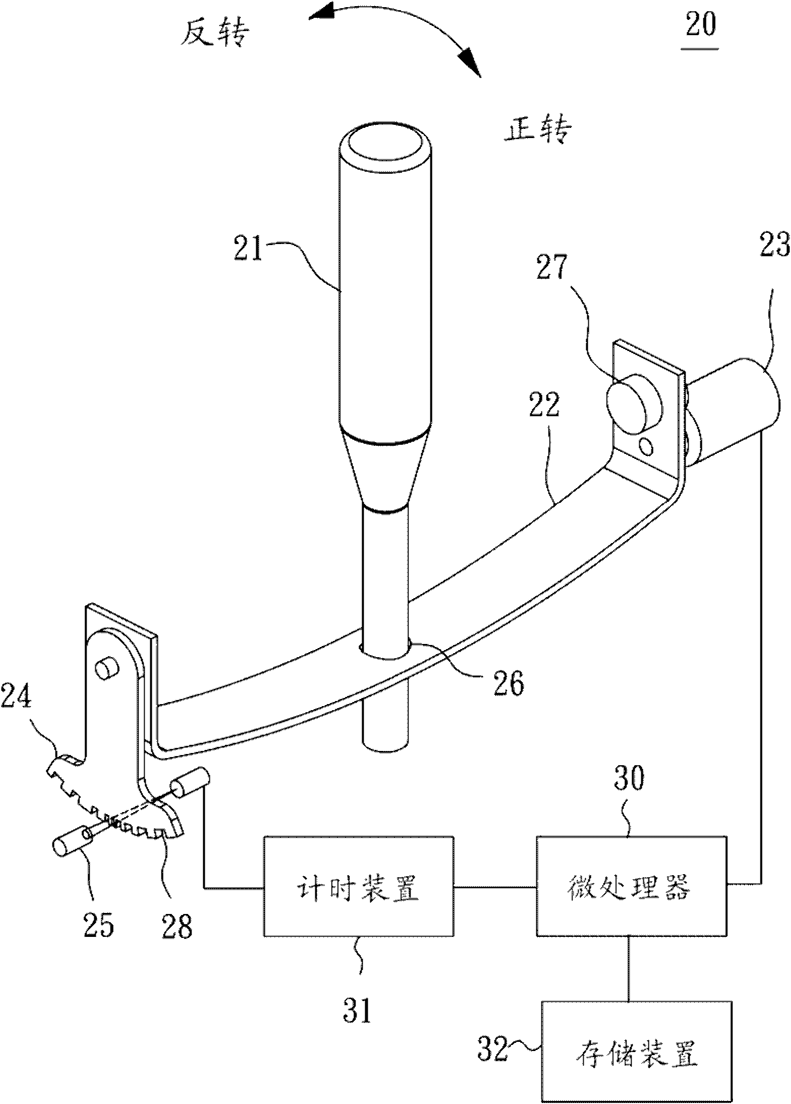
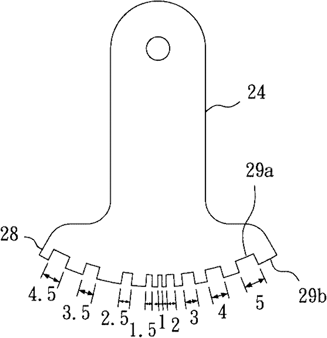
[0035] Please also see figure 2 , image 3 , Figure 4 and Figure 5 , figure 2 is the force feedback device of the first embodiment of the present invention, image 3 and Figure 4 For the rocker of the present invention, Figure 5 is the absolute position of the screen of the present invention. figure 2 Among them, the force feedback device 20 of the first embodiment of the present invention is in a one-dimensional form and mainly includes a joystick 21 , a rotating shaft 22 , a motor 23 , a rocker 24 and a sensor 25 . One end of the joystick 21 passes through the drive slot 26 in the middle of the rotating shaft 22 , and is movably pivotally connected to the force feedback device 20 . One end of the rotating shaft 22 is connected to a motor 23 to...


PUM


Abstract

The invention discloses a force feedback device and a positioning method thereof. The method comprises the following steps of: controlling a motor to rotate at a constant speed in a clockwise or anticlockwise direction by a microprocessor, so as to drive an unequally-spaced shielding grid to generate an opening or closing signal by a sensor; measuring the time of the opening or closing signal of the sensor by a timing device; calculating a shielding grid passing angle; comparing the shielding grid passing angle with an absolute storing angle of a storage device; and determining an absolute angle of the shielding grid so as to finish the positioning of an operating rod.

Description

technical field [0001] The invention relates to a force feedback device, in particular to a force feedback device for control, a positioning structure and a method for determining the position of a joystick when the force feedback device is activated. Background technique [0002] A force feedback device (Force Feedback Device) mainly integrates multiple joysticks, buttons or knobs with different control functions into one joystick. The moving range of the joystick is divided into multiple control function areas, and different force feedback types are given to different control function areas to prompt the current control function of the joystick, so as to simplify the control method and structure. [0003] like figure 1 As shown, it is the US7490530 patent case announced by the United States. The background technology discloses a force feedback device 10. A joystick 11 simultaneously operates two-dimensional rotating shafts 12a and 12b. One end of each rotating shaft is p...

Claims


Application Information

Patent Timeline
IPC IPC(8): G05G9/047
Inventor 黄建彰黄识忠
Owner QUANTA STORAGE INC
Learn More