Capacitive pressure sensor

A capacitive, pressure gauge technology used in the measurement of fluid pressure through electromagnetic elements, fluid pressure measurement using inductive changes, and fluid pressure measurement

Active Publication Date: 2012-12-05
MKS INSTR INC
View PDF15 Cites 1 Cited by
  • Summary
  • Abstract
  • Description
  • Claims
  • Application Information

AI Technical Summary

Problems solved by technology

[0007] The disadvantage of using a very narrow gap is that a small change in the shape of the electrode gap that is not related to the measured pressure difference across the diaphragm is also detected

Method used


Image

  • Capacitive pressure sensor
  • Capacitive pressure sensor
  • Capacitive pressure sensor

Examples


Embodiment Construction

[0038] Illustrative embodiments are now discussed. Other embodiments may additionally or alternatively be used. Details that may be obvious or not necessary may be omitted to save space or for a more effective presentation. Rather, some embodiments may be practiced without all of the disclosed details.

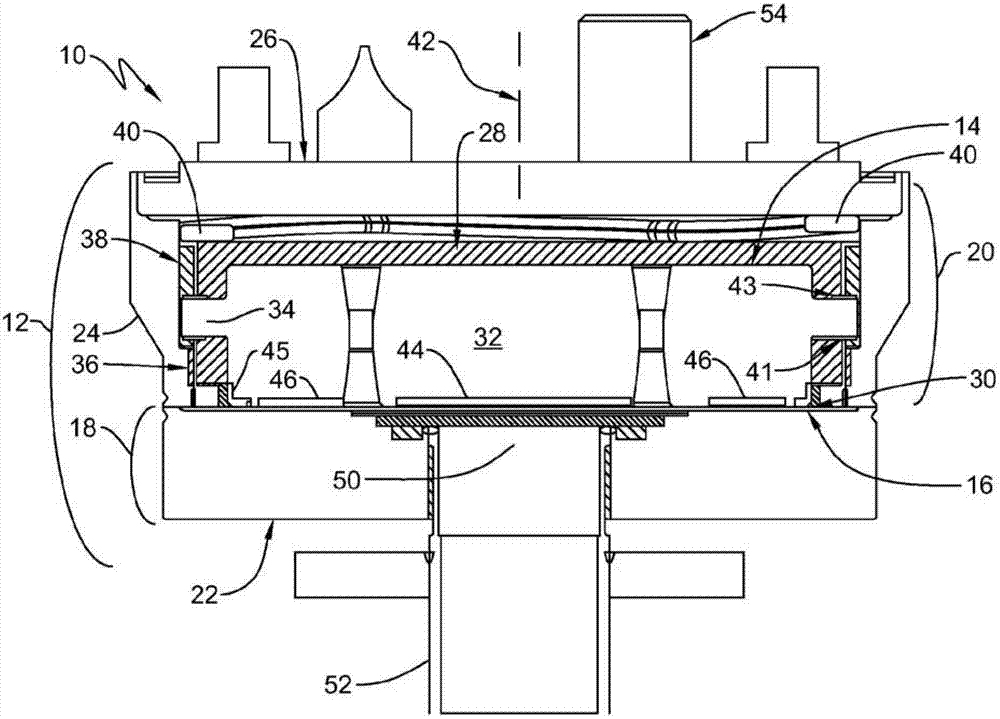
[0039] figure 1The capacitive manometer 10 shown in includes a housing 12 for supporting a fixed electrode structure 14 and a resilient diaphragm 16 . Housing 12 may include a process housing portion 18 and a reference housing portion 20 separated by a resilient membrane 16 . The process housing portion 18 includes a Px cover 22 . Reference housing part 20 includes ring 24 and Pr cap 26 . In the illustrated embodiment, the ring 24 of the reference housing portion 20 includes a hollow cavity 28 for receiving and supporting the fixed electrode structure 14 and resilient diaphragm 16 in a predetermined relationship, thereby maintaining them as defined by a gap 30 of predeter...


PUM


Abstract

An improved capacitive manometer, the manometer comprises: a diaphragm including (a) a common electrode and (b) an electrode structure including a center electrode and ring electrode, wherein the diaphragm is movable between (i) a zero position when the pressure on each side of the diaphragm is the same and (ii) a maximum differential position when the maximum measurable differential pressure is applied to the diaphragm, and a support structure arranged so as to support the diaphragm so that the diaphragm is constrained relative to the electrode structure, and the common electrode is spaced from and axially aligned with the center and ring electrodes relative to an alignment axis of the manometer; wherein the electrode structure is secured relative to the diaphragm at least three clamping locations angularly spaced around the alignment axis; and wherein the angle defined within each right plane containing a point of constraint of the diaphragm and the point of each clamping location relative to the plane of the diaphragm in the zero position is between 60 DEG and 90 DEG so as to reduce changes in electrode disk support height, enable smaller gaps and improved stability between the diaphragm and electrode structure. An additional improvement is provided by including a spacer ring including a plurality of tabs; and a clamp arranged to clamp the electrode structure to the spacer ring at the location of each of the tabs so as to define a plurality of equiangularly spaced, clamped locations around the alignment axis, so as to eliminate the possibility of an occasional spacer induced radial shear force and subsequent potential stick slip condition that could impact repeatability and stability.

Description

[0001] Cross References to Related Applications [0002] This application is based on and claims U.S. Provisional Patent entitled "CAPACITIVE PRESSURE SENSOR" filed February 2, 2010 by Steven D. Blankenship and assigned to the present assignee, Docket No. 056231-0984 (MKS-217PR) Priority to application 61 / 300,620, which is hereby incorporated by reference in its entirety. technical field [0003] The present invention relates generally to a capacitive pressure sensor, and more particularly to an improved sensor which provides very accurate and precise pressure measurements, especially at very low pressures (vacuum). Background technique [0004] Pressure transducers have been employed in a large number of applications. One such transducer is a capacitance manometer, which provides an accurate and precise measurement of the pressure of a gas, vapor or other fluid. Applications include precise control of vacuum-based processing and semiconductor processing controls. Example...

Claims


Application Information

Patent Timeline
IPC IPC(8): G01L9/00
CPCG01L9/0072G01L9/0042G01L9/10G01L9/00G01L19/00
Inventor S·D·布兰肯希普
Owner MKS INSTR INC
Why Eureka
Try Eureka