Novel pouring structure for mould

A new type of mold and gate technology, applied in the field of mold processing, can solve the problems of easy deformation of the gate, and achieve the effect of improving the yield rate and reducing the instantaneous momentum

Inactive Publication Date: 2012-12-12
SHENGYANG PRECISION MOLD KUSN
View PDF4 Cites 6 Cited by
  • Summary
  • Abstract
  • Description
  • Claims
  • Application Information

AI Technical Summary

Problems solved by technology

However, in the existing gate design, when the temperature of the rubber material is high and the acceleration of the rubber material is high, the gate is easily deformed.

Method used


Image

  • Novel pouring structure for mould

Examples


Embodiment Construction

[0011] In order to clarify the technical scheme and technical purpose of the present invention, the present invention will be further introduced below in conjunction with the accompanying drawings and specific implementation methods.

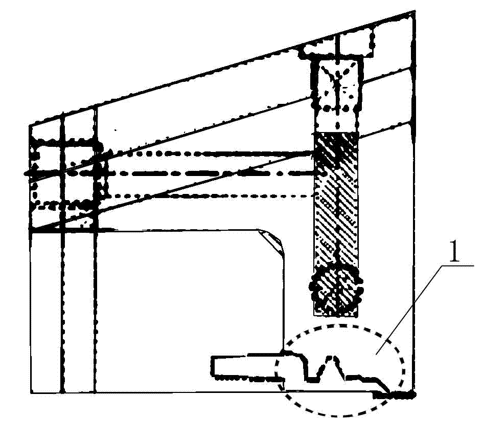
[0012] As shown in the figure, a new type of mold pouring structure includes a main channel, a branch channel and a gate channel 1 connecting the branch channel and the cavity. The gate channel 1 has an irregular cavity, The wall surface of the cavity is provided with depressions or protrusions, and the depressions and protrusions are curved or formed by a combination of slopes and planes.

[0013] like figure 1 As mentioned above, a buffer transition cavity is provided in the middle of the gate runner 1, and the buffer transition cavity is concave upward. When the colloid enters, a part of the colloid continues to flow forward, while the other part can temporarily store in the buffer transition cavity. In the transition cavity, reduce the impu...


PUM


Abstract

The invention discloses a novel pouring structure for a mould, comprising a main flow channel, branch flow channels, and pouring gate flow channels for connecting the branch flow channels with the main flow channel. The novel pouring structure is characterized in that the pouring gate flow channels are provided with irregular cavities, and recesses or bulges are arranged on the wall surfaces of the cavities. According to the invention, the instantaneous flow acceleration during glue inlet is slowed down, and the partial impact pressure on the pouring gate flow channels during the glue inlet is reduced by increasing the areas of the tube walls of the pouring gate flow channels, thus preventing the mould from deforming.

Description

technical field [0001] The invention belongs to the field of mold processing, in particular to a novel mold pouring structure. Background technique [0002] The gate, also known as the feed port, is the narrow opening between the runner and the cavity on the mold, and it is also the shortest part. Its function is to make the molten material accelerate when it enters the cavity, which is conducive to rapid filling. Cavity, after molding, the plastic at the gate condenses first to close the cavity, prevent the molten plastic from flowing back, and avoid the pressure of the cavity from dropping too fast, so that shrinkage cavities or depressions occur on the product. After molding, it is easy to separate the pouring material from the product. Commonly used gate runners are rectangular, cylindrical or tapered horn-shaped, and the runners are basically regularly changing cavities. However, in the existing gate design, when the temperature of the rubber material is high and the a...

Claims


Application Information

Patent Timeline
Patent Type & Authority Applications(China)
IPC IPC(8): B29C45/27B29C45/73
Inventor 黄小兵陈宗慧杨振
Owner SHENGYANG PRECISION MOLD KUSN
Why Eureka
Try Eureka