Fireproof air exhaust duct inlet voltage transformation flow guide device

A technology of diversion devices and exhaust ducts, applied in vertical pipes, building components, buildings, etc., can solve problems such as increasing the resistance and static pressure of exhaust ducts, reducing the exhaust force of range hoods, and affecting exhaust efficiency. To achieve the effect of unobstructed smoke exhaust, reduce smoke exhaust resistance, and improve space utilization

Inactive Publication Date: 2012-12-12
HANGZHOU XIAOMI ENVIRONMENTAL SCI & TECH
View PDF10 Cites 5 Cited by
  • Summary
  • Abstract
  • Description
  • Claims
  • Application Information

AI Technical Summary

Problems solved by technology

[0003] The present invention aims at the part of the fire-proof exhaust extending into the exhaust duct in the prior art, which will occupy the area of ​​the exhaust duct when the residents on the floor do not exhaust smoke, and indirectly increase the resistance and static pressure inside the exhaust duct, making the The exhaust air force of the range hood is reduced, which affects the exhaust efficiency and other shortcomings. When the residents on the floor do not exhaust smoke, the back deflector of the deflector device is in a vertical state, parallel to the inner wall of the exhaust duct, and will not Occupies the area of ​​the exhaust duct; when exhausting, the back deflector forms a certain angle with the inner wall of the exhaust duct to form a diversion pipe structure, which can accelerate the upward guidance and discharge of the smoke.

Method used


Image

  • Fireproof air exhaust duct inlet voltage transformation flow guide device
  • Fireproof air exhaust duct inlet voltage transformation flow guide device
  • Fireproof air exhaust duct inlet voltage transformation flow guide device

Examples


Embodiment 1

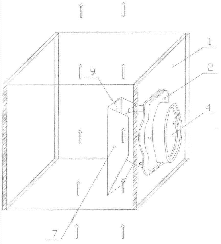
[0035] Pressure-changing diversion device at the inlet of the fire-proof exhaust duct, such as Figure 1 to Figure 4 As shown, it includes a fire check valve 2 arranged on the exhaust duct 1, and the fire check valve 2 is connected to the outer wall of the exhaust duct 1 through a connecting panel, and also includes a deflector device 9, and a right wing plate 51 and a left wing plate 52 , Deflector device 9, exhaust duct 1 inner wall, right wing plate 51 and left wing plate 52 four form a closed around, the ventilation duct that runs through up and down. The fire check valve 2 includes a valve plate 4 and an air inlet 3 .

[0036] The right wing 51 and the left wing 52 are connected to the fire check valve 2 , and the deflector device 9 is hinged to the right wing 51 and the left wing 52 through the rotating shaft 7 .

[0037] The deflector device 9 includes a right deflector 91 , a left deflector 92 and a rear deflector 10 , and the right deflector 91 and the left deflector...

Embodiment 2

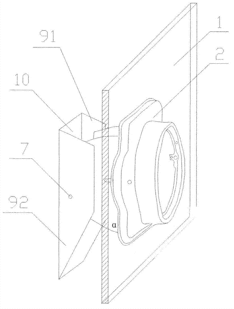
[0040] Pressure-changing diversion device at the inlet of the fire-proof exhaust duct, such as Figures 2 to 8 As shown, it includes a fire check valve 2 arranged on the exhaust duct 1, a deflector device 9, and a right wing 51 and a left wing 52, the deflector device 9, the inner wall of the exhaust duct 1, and the right wing 51 Four of the left wing plate 52 form a closed all around, the ventilation duct that runs through up and down.

[0041] The right wing 51 and the left wing 52 are connected to the fire check valve 2 , and the deflector device 9 is hinged to the right wing 51 and the left wing 52 through the rotating shaft 7 .

[0042] The deflector device 9 includes a right deflector 91 , a left deflector 92 and a rear deflector 10 , and the right deflector 91 and the left deflector 92 are respectively hinged to the right wing 51 and the left wing 52 through the rotating shaft 7 .

[0043] The height of the rotating shaft 7 is lower than the height of the horizontal midl...

Embodiment 3

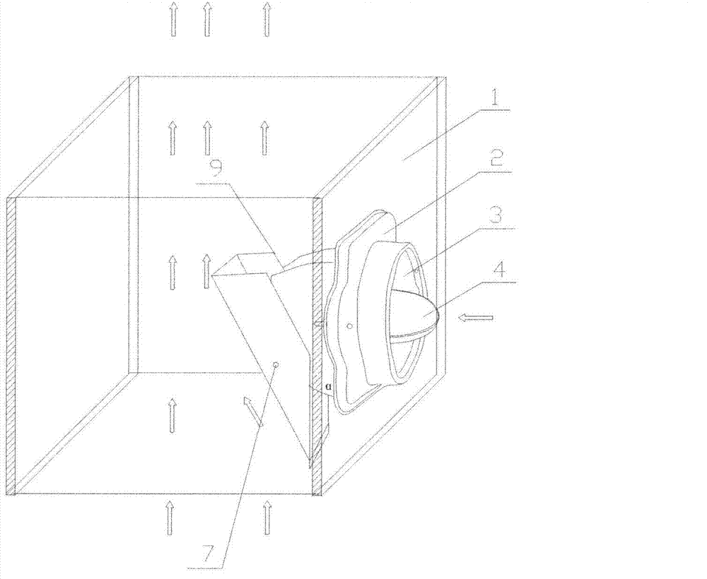
[0046] Pressure-changing diversion device at the inlet of the fire-proof exhaust duct, such as Figure 9 , 10 As shown, in the present embodiment, the deflector device 9 includes a back deflector 10, the back deflector 10 is respectively hinged with the right wing plate 51 and the left wing plate 52 through the rotating shaft 7, and the lower side of the back deflector 10 is provided with a balance plate 8.


PUM


Abstract

The invention relates to an air exhaust duct inlet flow guide device, and discloses a fireproof air exhaust duct inlet voltage transformation flow guide device which comprises a fireproof stop valve (2) arranged on an air exhaust duct, a flow guide plate device (9) as well as a right wing plate (51) and a left wing plate (52); the fireproof stop valve (2) is connected with an outer wall of the air exhaust duct (1) through a connecting panel; the flow guide plate device (9), an inner wall of the air exhaust duct (1), the right wing plate (51) and the left wing plate (52) form a ventilating pipeline which is sealed in periphery and runs through from top to bottom. According to the invention, when a range hood is opened, a valve sheet of the fireproof stop valve and the flow guide plate device are pushed away through wind force and pressure, thus the flow guide plate rotates into a flow guide form, which is beneficial to flue gas discharge; and after the range hood is closed, the valve sheet is closed, a back flow guide plate of the flow guide device is parallel to the air exhaust duct, the internal air exhaust space of the air exhaust duct is not occupied, the air exhaust duct space utilization ratio is improved greatly, and the flue gas discharge is more smooth.

Description

technical field [0001] The invention relates to an inlet flow guiding device of an exhaust passage, in particular to a pressure-changing flow guiding device for a fire-proof exhaust passage inlet. Background technique [0002] In the residential kitchen and bathroom centralized exhaust duct system, in order to make the oil fume enter the exhaust duct in the same direction as the flue gas flow, a guide pipe is installed at the entrance of the exhaust duct. According to the size of the exhaust duct, the guide pipe and the transformer plate occupy 10-50% of the cross-sectional area of ​​the exhaust duct, such as the invention patent 00128214. The "parallel variable pressure and exhaust gas exhaust structure" accounts for 20% of the cross section of the exhaust duct. These structures reduce the ventilation area of ​​the exhaust duct, indirectly increase the resistance and static pressure inside the exhaust duct, and make the range hood The air exhaust force is reduced. If the s...

Claims


Application Information

Patent Timeline
Patent Type & Authority Applications(China)
IPC IPC(8): E04F17/02
Inventor 王启定曹正祥
Owner HANGZHOU XIAOMI ENVIRONMENTAL SCI & TECH
Why Eureka
Try Eureka