Bearing cover for crank circular slider mechanism as well as internal-combustion engine and compressor using bearing cover

A technology of crank round slider and bearing cap, applied in the fields of bearing caps and compressors, can solve problems such as difficulty in setting reciprocating motion orbits

Inactive Publication Date: 2012-12-12
BEIJING SINOCEP ENGINE TECH
View PDF12 Cites 3 Cited by
  • Summary
  • Abstract
  • Description
  • Claims
  • Application Information

AI Technical Summary

Problems solved by technology

And the body of prior art is difficult t...

Method used


Image

  • Bearing cover for crank circular slider mechanism as well as internal-combustion engine and compressor using bearing cover
  • Bearing cover for crank circular slider mechanism as well as internal-combustion engine and compressor using bearing cover
  • Bearing cover for crank circular slider mechanism as well as internal-combustion engine and compressor using bearing cover

Examples


Embodiment Construction

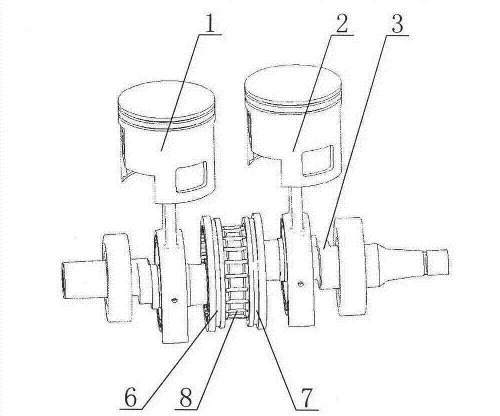
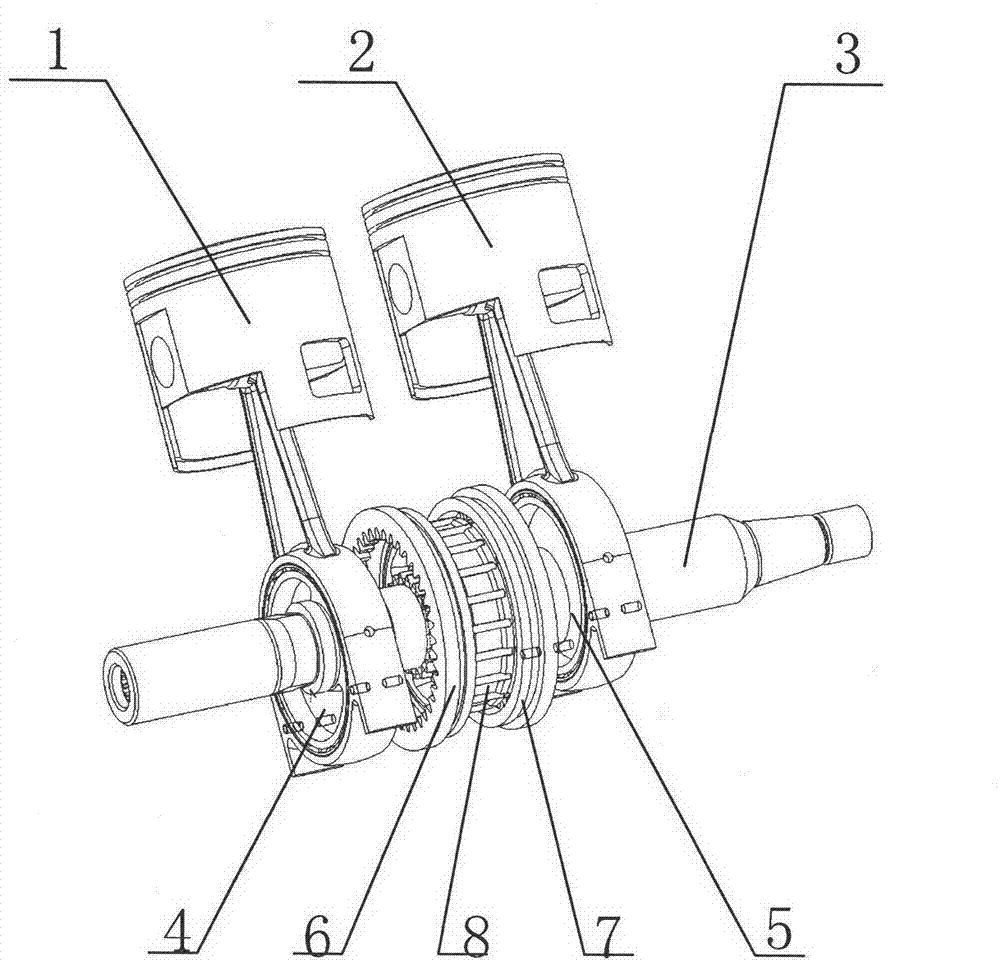
[0031] Please see figure 1 , which is one of the three-dimensional views of the structure of the crank-slider mechanism applied to the bearing cover of the crank-slider mechanism provided by the embodiment of the present invention; please also refer to figure 2 , which is the second structural perspective view of the crank circular slider mechanism.

[0032] like figure 1 , figure 2 As shown, the crank and slider mechanism includes a first piston 1 , a second piston 2 , a crankshaft 3 , a first slider 4 , a second slider 5 , a first ring gear 6 and a second ring gear 7 . The above-mentioned components are introduced respectively below.

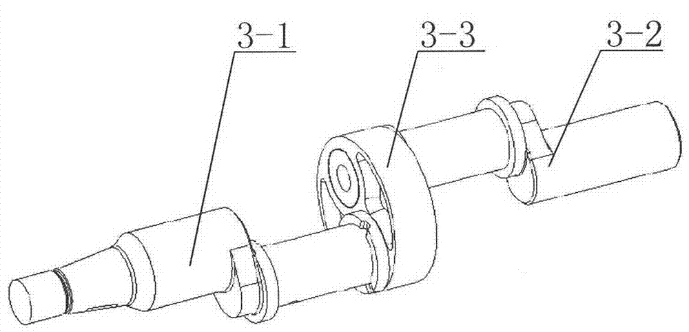
[0033] Please see image 3 , which shows the structure of the crankshaft 3 .

[0034] As shown in the figure, the crankshaft 3 is a split crankshaft, including a first crankshaft segment 3-1, a second crankshaft segment 3-2 and an intermediate crank 3-3.

[0035] Please see Figure 4 , which is a perspective view of the middle crank 3...


PUM


Abstract

The invention provides a bearing cover for a crank circular slider mechanism. The bearing cover is matched up with an engine body so as to form a complete engine body for supporting the crank circular slider mechanism; a cavity for the piston to do reciprocating motion is arranged on the bearing cover and runways are arranged on two sides of the cavity, and the runways are used for providing a guide track of the reciprocating motion for a guide track surface at the lower part of the piston of the crank circular slider mechanism. The bearing cover is capable of solving the problem of lower reciprocating motion guidance of the piston movement, so that the reciprocating motion of the piston is stably continued. The invention simultaneously provides an internal-combustion engine and a compressor by using the bearing cover.

Description

technical field [0001] The invention relates to a crank circular slider mechanism, in particular to a bearing cover for a crank circular slider mechanism. The present invention also provides an internal combustion engine using the above-mentioned bearing cover and a compressor using the above-mentioned bearing cover. Background technique [0002] In a traditional internal combustion engine, the reciprocating motion of the piston is converted into the rotational motion of the crankshaft through the crank-link mechanism, and then the crankshaft drives the corresponding moving parts to output power externally. In the traditional compressor, there is also a crank-link mechanism, through which the rotational motion of the crankshaft is converted into the reciprocating motion of the piston, and the air in the cylinder is compressed by the piston. However, in the crank-link mechanism, due to the existence of the connecting rod, the internal combustion engine and the compressor of ...

Claims


Application Information

Patent Timeline
IPC IPC(8): F16H57/02F16H21/18F16C35/00F02B75/32F04B39/00
Inventor 黎明黎正中杨之怡王清旭郭立军
Owner BEIJING SINOCEP ENGINE TECH
Why Eureka
Try Eureka