Vacuum operating platform with damping mechanism

A technology of vibration damping mechanism and operation platform, applied in the field of ultra-precision measurement, can solve the problem that the effect of vibration damping device does not conform to the high stability vacuum measurement platform, etc., and achieve the effect of reducing vibration, ensuring vacuum environment and ensuring sealing performance

Active Publication Date: 2012-12-12
KYKY TECH
View PDF10 Cites 7 Cited by
  • Summary
  • Abstract
  • Description
  • Claims
  • Application Information

AI Technical Summary

Problems solved by technology

[0007] The technical problem to be solved by the present invention is that the effect of the damping device used to buffer the vibration transmission in the vacuum operating platform in the prior art does not meet the requirements of a high-stable vacuum measurement platform, and then provide a vibration-reducing device that can meet the requirements of an ultra-precision measurement platform. Vacuum operating platform for vibration mechanism

Method used


Image

  • Vacuum operating platform with damping mechanism
  • Vacuum operating platform with damping mechanism
  • Vacuum operating platform with damping mechanism

Examples


Embodiment 1

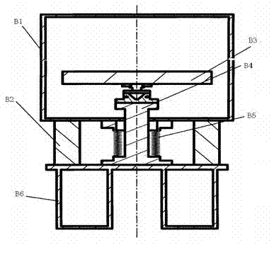
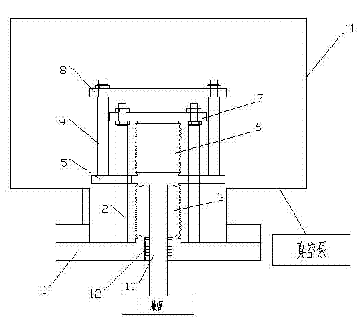
[0037] This embodiment provides a vacuum operating platform with a vibration damping mechanism, such as image 3 As shown, it includes a platform support plate 5, which is fixed on the ground through a pillar 10. In this embodiment, the platform support plate 5 is fixed on the ground, and the platform support plate 5 can also be fixed in the actual application process. 5. Be fixed on a very heavy and stable platform. Above the platform support plate 5, a measurement platform 8 is arranged, and the measurement platform 8 is fixedly connected with the platform support plate 5 by at least two symmetrical fixtures 9 about the center of the measurement platform 8, in order to reduce the structure In this embodiment, two fixing members 9 are used to fix the measurement platform, and there is a certain distance between the measurement platform 8 and the platform support plate 5 .

[0038]As shown in the figure, the damping mechanism includes: at least two auxiliary supports 2 that a...

Embodiment 2

[0041] This embodiment is an improvement of Embodiment 1. In this embodiment, the structures of the lower bellows 3 and the upper bellows 6 are selected to be exactly the same.

[0042] Moreover, in order to ensure the sealing effect when installing the operating platform, welding can be used for the fixed connection, and other ways can be selected for fixing for some mechanisms that are already in a vacuum environment.

[0043] Therefore, as an optional embodiment, the upper bellows 6 is welded to the platform support plate 5 and the damping flange 7 . The lower bellows 3 is welded to the platform support plate 5 and the sealing flange 1 .

[0044] Since the measurement platform 8 is already in a vacuum environment, the measurement platform 8 can be fixed on the platform support plate 5 by welding or by other methods. In this embodiment, the fixing member 9 is selected as a screw and a nut used in conjunction, one end of the screw is fixed on the platform support plate 5, an...


PUM


Abstract

The invention discloses a vacuum operating platform with a damping mechanism, wherein the vacuum operating platform is fixedly connected with a sealing flange through a vacuum chamber shell; the sealing flange is fixedly connected with a damping flange; an upper corrugated pipe is fixedly connected between a platform supporting plate and the damping flange; and a lower corrugated pipe is fixedly connected between the sealing flange and the platform supporting plate. When vibration is generated, the vacuum chamber shell transfers the vibration to the sealing flange; the sealing flange directly transfers the vibration to the lower corrugated pipe; meanwhile, the vibration of the sealing flange is transferred to the damping flange through an auxiliary supporting part and then transferred to the upper corrugated pipe; the damping flange can be regulated along the axial direction of the auxiliary supporting part so as to regulate deformation of the upper corrugated pipe and the lower corrugated pipe; and therefore, the vibration force of the upper corrugated pipe transferring to the platform supporting plate is opposite to the vibration force of the lower corrugated pipe transferring to the platform supporting plate. As a result, the vibration of the platform supporting plate is effectively reduced.

Description

technical field [0001] The invention relates to the technical field of ultra-precision measurement, in particular to a vacuum operating platform with a vibration damping mechanism. Background technique [0002] Vibration is a big nuisance for ultra-precision measurement platforms. With the development of science and technology, more and more scientific experiments need to be carried out in a vacuum environment. It is particularly important to place the ultra-precision measurement platform in a vacuum environment to ensure its original accuracy. [0003] In order to ensure that the measurement platform is in a vacuum environment, it is often necessary to set the measurement platform in a vacuum chamber, and the gas in the vacuum chamber is evacuated by a vacuum pump connected to the vacuum chamber to ensure that the vacuum chamber is in a vacuum environment. The vacuum pump will inevitably generate vibration during operation and transmit the vibration to the vacuum cavity. S...

Claims


Application Information

Patent Timeline
Patent Type & Authority Applications(China)
IPC IPC(8): G01D11/30G01D11/10
Inventor 曹桂英
Owner KYKY TECH
Why Eureka
Try Eureka