Encoder base and encoder using same
A technology of encoders and bases, applied in the field of encoders, can solve the problems of inability to inject molding, increase the thickness of encoders, and easy gaps, etc., and achieve the effect of saving material costs, saving assembly man-hours, and reducing overall thickness
- Summary
- Abstract
- Description
- Claims
- Application Information
AI Technical Summary
Problems solved by technology
Method used
Image

Examples
Embodiment Construction
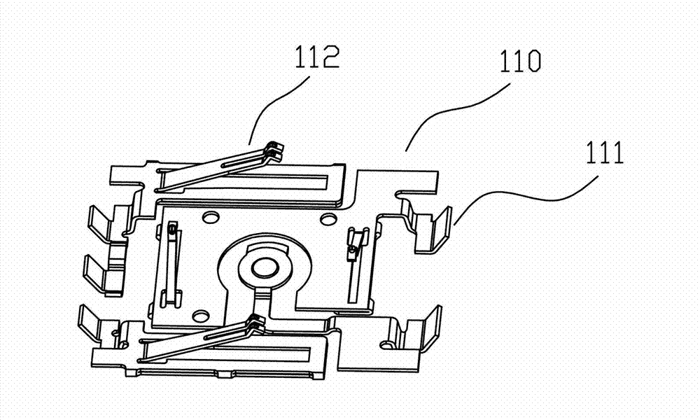
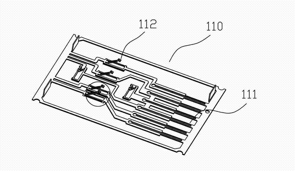
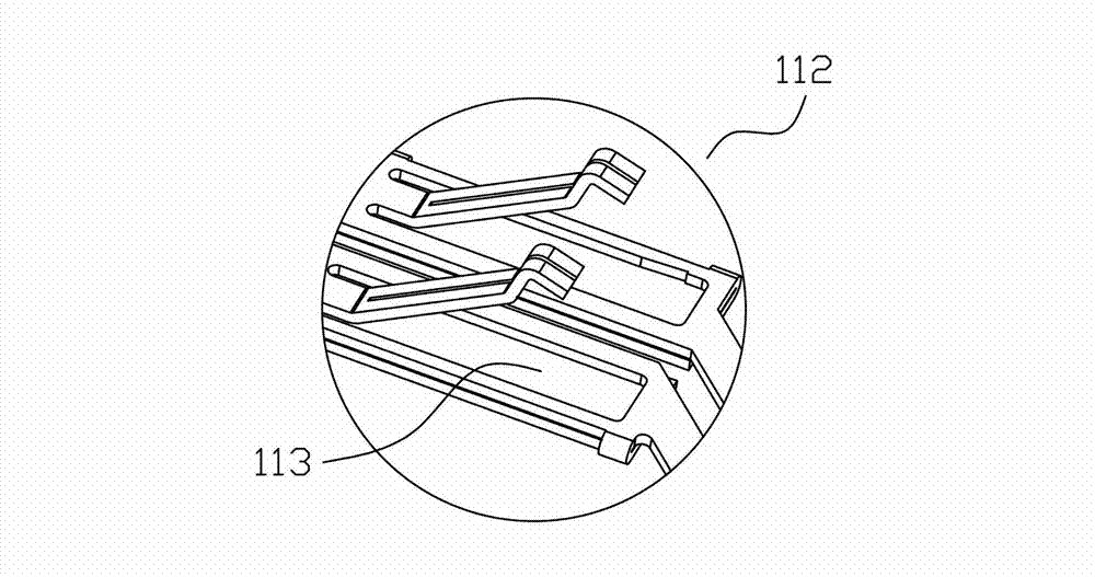
[0020] refer to Figure 1 to Figure 5 The structure of the terminal hardware sheet and the encoder base is shown. The encoder base 100 includes several sets of terminal hardware sheets 110 and a plastic body 120 overmolded outside the terminal hardware sheet 110. The terminal hardware sheet 110 includes terminals 111 and brushes. part 112, the brush of the brush part 112 is higher than the plane of the brush part due to stamping and forming, and there is a space under the brush part. There is an extension part 113 on the side of the brush part 112, and the extension part 113 is bent and attached to the The bottom surface of the brush part 112 covers the void, and the plastic body 120 encapsulates the brush part 112 and the extension part 113 as a whole.
[0021] refer to Figure 6 An encoder is shown, which includes a base 210, a code disc 220 in contact with the brush portion in the accommodating cavity of the base 210, a rotating shaft 230 inserted in the central hole of th...
PUM
 Abstract
Description
Claims
Application Information
PatSnap Eureka turns technology decisions into work you can execute. Powered by our Innovation Knowledge Graph, it runs expert workflows across engineering, life sciences, materials and intellectual property. Get your review-ready output in minutes.


