Processing method and device capable of keeping uplink synchronization of terminals in DRX mode
A terminal and mode technology, applied in the communication field, can solve the problem that the UE cannot receive the TA command, and achieve the effect of optimizing the utilization rate and reducing the uplink out-of-synchronization.
- Summary
- Abstract
- Description
- Claims
- Application Information
AI Technical Summary
Problems solved by technology
Method used
Image

Examples
Embodiment Construction
[0032] In order to make the technical problems, technical solutions and beneficial effects to be solved by the present invention clearer and clearer, the present invention will be further described in detail below in conjunction with the accompanying drawings and embodiments. It should be understood that the specific embodiments described here are only used to explain the present invention, not to limit the present invention.
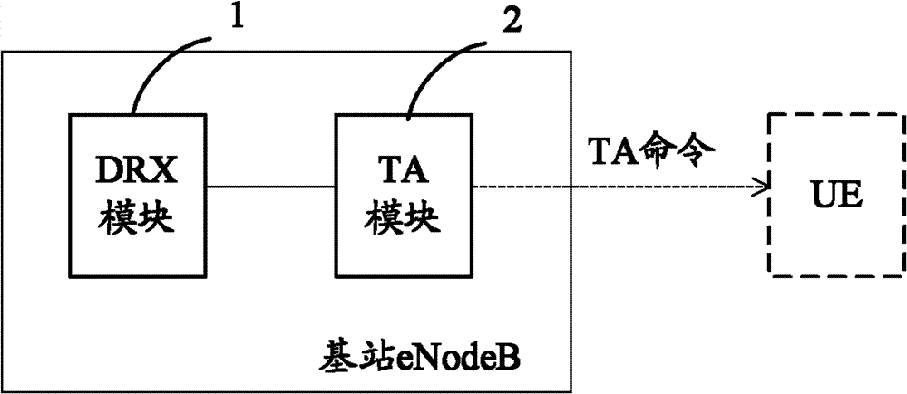
[0033] figure 2 is a schematic structural diagram of an evolved base station according to an embodiment of the present invention. Such as figure 2 As shown, the base station eNodeB may include: a DRX module 1 and a TA module 2, wherein the DRX module 1 is used to maintain the start and stop of DRX timers and the state transition of the UE, and at the same time maintain the time counter for when the UE does not schedule data and the UE is in DRX inactive time counter; TA module 2, used to maintain the TATimer timer, obtain relevant configuration info...
PUM
 Abstract
Description
Claims
Application Information
PatSnap Eureka turns technology decisions into work you can execute. Powered by our Innovation Knowledge Graph, it runs expert workflows across engineering, life sciences, materials and intellectual property. Get your review-ready output in minutes.


