Butt-jointing method for truss girder

A technology of truss girders and main girders, which is applied in the field of bridge construction, can solve the problems of reducing the efficiency of truss girder erection, complicating the processing process of truss girders, confusing truss girders, etc., and achieving the effects of improving construction efficiency, great manufacturing flexibility, and flexible erection

Active Publication Date: 2015-06-10
CHINA RAILWAY 23RD BUREAU GRP THIRD ENG CO LTD
View PDF7 Cites 0 Cited by
  • Summary
  • Abstract
  • Description
  • Claims
  • Application Information

AI Technical Summary

Problems solved by technology

[0003] In the installation process of the existing truss girders, the two ends of the truss girders are supported by the bridge piers respectively, and are carried on two adjacent bridge piers, so that the butt joint operation of the two adjacent truss girders connected to each other can only be performed at The length of each truss girder must strictly correspond to the distance between the two bridge piers, that is, the lengths of the truss girders supported on different bridge piers are different due to the distance between the bridge piers. The truss girders of different lengths are processed to form truss girders of different lengths, which complicates the processing of the truss girders. Moreover, during the erection of the truss girders, if the corresponding truss girders between two specific piers are confused, the corresponding truss girders need to be replaced, reducing the In addition, the butt joint operation of two adjacent truss girders can only be carried out on the pier, and the space above the pier is limited. When the two truss girders are loaded on it, the remaining space is more There is a great potential safety hazard for the constructors to carry out construction in such a small space

Method used


Image

  • Butt-jointing method for truss girder

Examples


Embodiment Construction

[0018] The technical solutions in the embodiments of the present invention will be clearly and completely described below in conjunction with the accompanying drawings in the embodiments of the present invention. Obviously, the described embodiments are only a part of the embodiments of the present invention, rather than all the embodiments. Based on the embodiments of the present invention, all other embodiments obtained by those of ordinary skill in the art without creative work shall fall within the protection scope of the present invention.

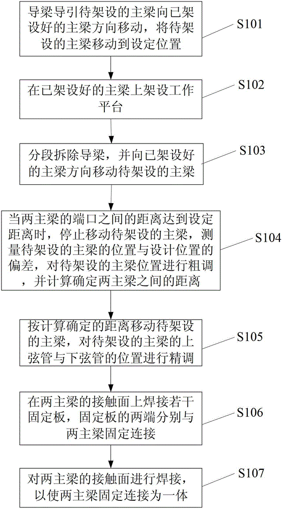
[0019] The docking method of the truss beam of the present invention mainly realizes the docking operation of the two main beams in the middle of the span (that is, in the air). For the specific docking operation steps, please refer to figure 1 :

[0020] Step S101: the guide beam guides the main beam to be erected to move in the direction of the erected main beam, and moves the main beam to be erected to a set position. In this step, whe...


PUM


Abstract

The invention discloses a butt-jointing method for a truss girder, which comprises the following steps of: a, guiding a to-be-erected girder to move along the direction of an erected girder till move to a preset position by a guiding girder; b, removing the guiding girder section by section and moving the to-be-erected girder along the direction of the erected girder; c, stopping moving when a distance between ports of the two girders reaches a preset distance, measuring a deviation between the position of the to-be-erected girder and a design position, roughly adjusting the position of the to-be-erected girder, and calculating and confirming the distance between the two girders; d, moving the to-be-erected girder according to the calculated and confirmed distance, and finely adjusting the positions of an upper chord pipe and a lower chord pipe of the to-be-erected girder, thereby aligning the two girders; and e, welding a plurality of fixing plates on a contact surface of the two girders, wherein the two ends of the fixing plates are respectively in fixed connection with the two girders. According to the butt-jointing method for the truss girder provided by the invention, the girders can be butt-jointed in air, the manufacturing of the girder and the butt-jointing operation application are more convenient and flexible, and the safety coefficient of the butt-jointing operation is also increased.

Description

Technical field [0001] The invention relates to the field of bridge construction, in particular to a method for connecting truss beams. Background technique [0002] As we all know, during the construction of the bridge, the truss girder (that is, the main girder) is sequentially installed on the piers that have been built. After all the truss girders are installed, the truss girder and the pier together form the main structure of the entire bridge. Subsequent construction of the entire bridge can be completed by laying (or pouring) the bridge deck on the truss girder. Therefore, the installation of the truss girder is an important part of the entire bridge construction process. The quality of the truss girder installation directly affects the entire bridge. Construction Quality. [0003] In the installation process of the existing truss girder, the two ends of the truss girder are supported by the piers as the supporting points, and they are carried on two adjacent piers, so that...

Claims


Application Information

Patent Timeline
Patent Type & Authority Patents(China)
IPC IPC(8): E01D21/00
Inventor 李治强杨毅王岑申瑞烂巨建基徐仁华杨肃钟张晓飞张旭董凤杰周川岭樊建国李文芳
Owner CHINA RAILWAY 23RD BUREAU GRP THIRD ENG CO LTD
Why Eureka
Try Eureka