Transmission device

A transmission device and transmission shaft technology, applied in the direction of transmission device parts, belts/chains/gears, mechanical equipment, etc., can solve the problems of efficiency loss, leakage to the outside of the cavity, and inability to prevent pump room gas from entering the engine room, etc. Simple, high transmission efficiency

Active Publication Date: 2012-12-19
WUHAN MARINE MACHINERY PLANT
View PDF6 Cites 5 Cited by
  • Summary
  • Abstract
  • Description
  • Claims
  • Application Information

AI Technical Summary

Problems solved by technology

When the engine room and the pump room are in a vertical position, the transmission device is required to vertically connect the turbine and the cargo oil pump; if the existing transmission device is used, first, the sealing element cannot bear the weight of the lubricating oil, and the lubricating oil in the sealing chamber will leak To the outside of the cavity, so that the gas in the pump room cannot be blocked from entering the engine room; second, the transmission shaft runs at high speed in lubricating oil, which will cause efficiency loss; third, the specially arranged cooling unit makes the structure of the existing transmission device more complicated

Method used


Image

  • Transmission device
  • Transmission device
  • Transmission device

Examples


Embodiment

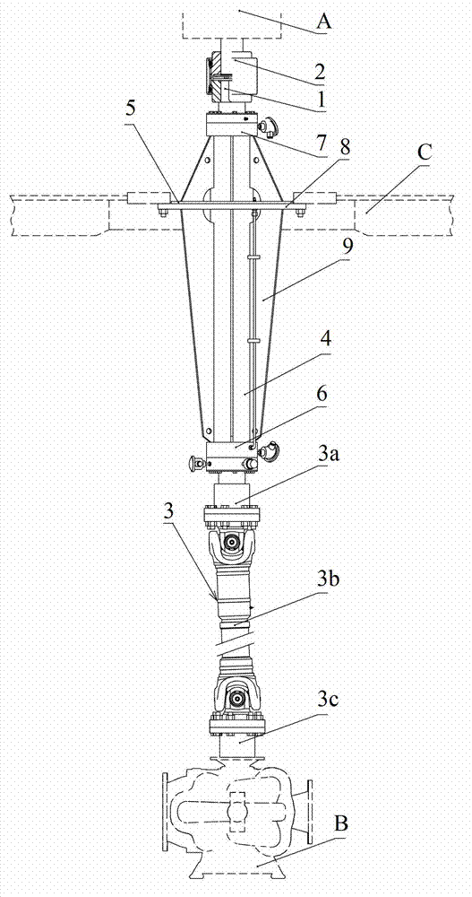
[0026] see figure 1 , The embodiment of the present invention provides a transmission device, which includes: a transmission shaft 1 and a sealing assembly. One end of the drive shaft 1 is provided with a coupling 2 for connecting the drive shaft 1 with the turbine A in the engine room; the other end of the drive shaft 1 is provided with a coupling 2 for connecting the drive shaft 1 with the cargo oil pump B in the pump room. Coupling set 3.

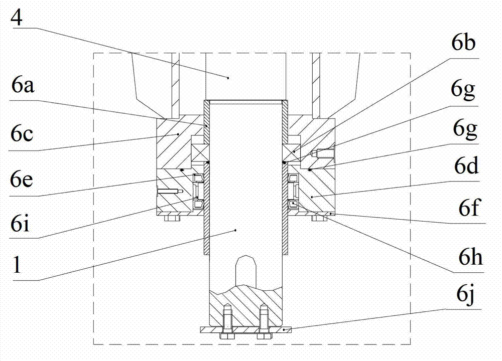
[0027] Wherein, the sealing assembly includes a supporting sleeve 4 for fixing on the partition C between the engine room and the pump room, and a first sealing unit 6 arranged at one end of the supporting sleeve 4 . The supporting sleeve 4 is sleeved on the transmission shaft 1 . see figure 2 , The first sealing unit 6 includes a first bearing 6b, a first bearing seat 6c, a first bearing cover 6d, a first rotary shaft seal 6e and a first sealing cover 6f. The first bearing 6b, the first rotary shaft seal 6e and the first seal cover...


PUM


Abstract

The invention discloses a transmission device, which belongs to the field of a ship machine. The transmission device comprises a transmission shaft and a sealing component; the sealing component comprises a supporting bushing which is fixed on a separation plate between an engine room and a pump room and a first sealing unit which is arranged on one end of the supporting bushing; the supporting bushing is sleeved on the transmission shaft; the first sealing unit comprises a first bearing, a first bearing seat, a first bearing cover, a first rotary shaft seal and a first sealing cover; the first bearing, the first rotary shaft seal and the first sealing cover are respectively sleeved on the transmission shaft; the first bearing seat is sleeved on the first bearing, and one end of the first bearing seat is connected with one end of the supporting bushing; the first bearing cover is sleeved on the first rotary shaft seal; and one end of the first bearing cover is in sealing connection with the other end of the first bearing seat, and the other end of the first bearing cover is connected with the first sealing cover. Due to the adoption of the transmission device, a turbine motor can be vertically connected with a cargo oil pump.

Description

technical field [0001] The invention relates to the field of ship machinery, in particular to a transmission device. Background technique [0002] On a large oil tanker, a special transmission device is required between the turbine and the cargo oil pump to realize the power transmission between the two. Generally, the turbine is placed in the engine room; the cargo oil pump is located in the pump room. Among them, in addition to the turbine, the engine room is also equipped with power sources such as motors, which is a non-hazardous area; while the pump room is filled with flammable and explosive gases volatilized from the cargo oil pump body, which is a hazardous area. In this environment, the transmission device is required not only to achieve reliable power transmission between the turbine and the cargo oil pump, but also to block the gas in the pump room from entering the engine room. [0003] Specifically, the prior art provides a transmission device, which mainly in...

Claims


Application Information

Patent Timeline
Patent Type & Authority Applications(China)
IPC IPC(8): F16H57/029F16H57/021F16H57/04
Inventor 陈斌万晓红吴震宇甘正林
Owner WUHAN MARINE MACHINERY PLANT
Why Eureka
Try Eureka