Oriented vibrating wheel system of driving gear box structure of road roller

A technology of gear box structure and vibrating wheel, which is applied in the field of road roller equipment, can solve problems such as shortening the service life of gears, uncoordinated vibration between teeth, and affecting meshing coordination, so as to reduce impact collision force and friction force, and compensate for coaxiality The effects of small errors and increased service life

Active Publication Date: 2014-08-27
合肥永安绿地工程机械有限公司
View PDF5 Cites 2 Cited by
  • Summary
  • Abstract
  • Description
  • Claims
  • Application Information

AI Technical Summary

Problems solved by technology

The structures of the current directional vibratory rollers all include a cylinder and a vibrating shaft fixed therein. The cylinder is supported by bearings to be fixed on the vibrating wheel. The inner chamber of the cylinder is arranged in sequence along the axis of the vibrating shaft with a plurality of independent shaft parts and shafts. The eccentric block group of the bearing, so as to realize the directional excitation effect of the vibration wheel through the forward and reverse rotation of each eccentric block group; the biggest defect of the above structure is that in the existing structure, the positive and negative rotation of each eccentric block group The realization of reverse vibration needs to rely on the direction-changing gear set composed of the stepped gear and the transition gear of the intermediate transmission part. Under the objective conditions that there are small errors in the coaxiality of parts processing and assembly, and the bearing clearances of the supporting bearings of vibration bearings, walking bearings, supporting vibration bearings, transition gears and stepped gears are different, its rigidity The matching method will greatly affect the meshing coordination between the transmission gears and the stepped gears and transition gears, resulting in many problems such as uncoordinated vibration between the teeth of the gears and instantaneous impact. The above rigid matching structure not only makes the roller vibrate during work It will generate greater impact and friction between the gears, which will greatly shorten the service life of the gears. At the same time, it will cut off the possibility of directly applying its structure to large-tonnage road rollers with directional vibration.

Method used


Image

  • Oriented vibrating wheel system of driving gear box structure of road roller
  • Oriented vibrating wheel system of driving gear box structure of road roller
  • Oriented vibrating wheel system of driving gear box structure of road roller

Examples


Embodiment Construction

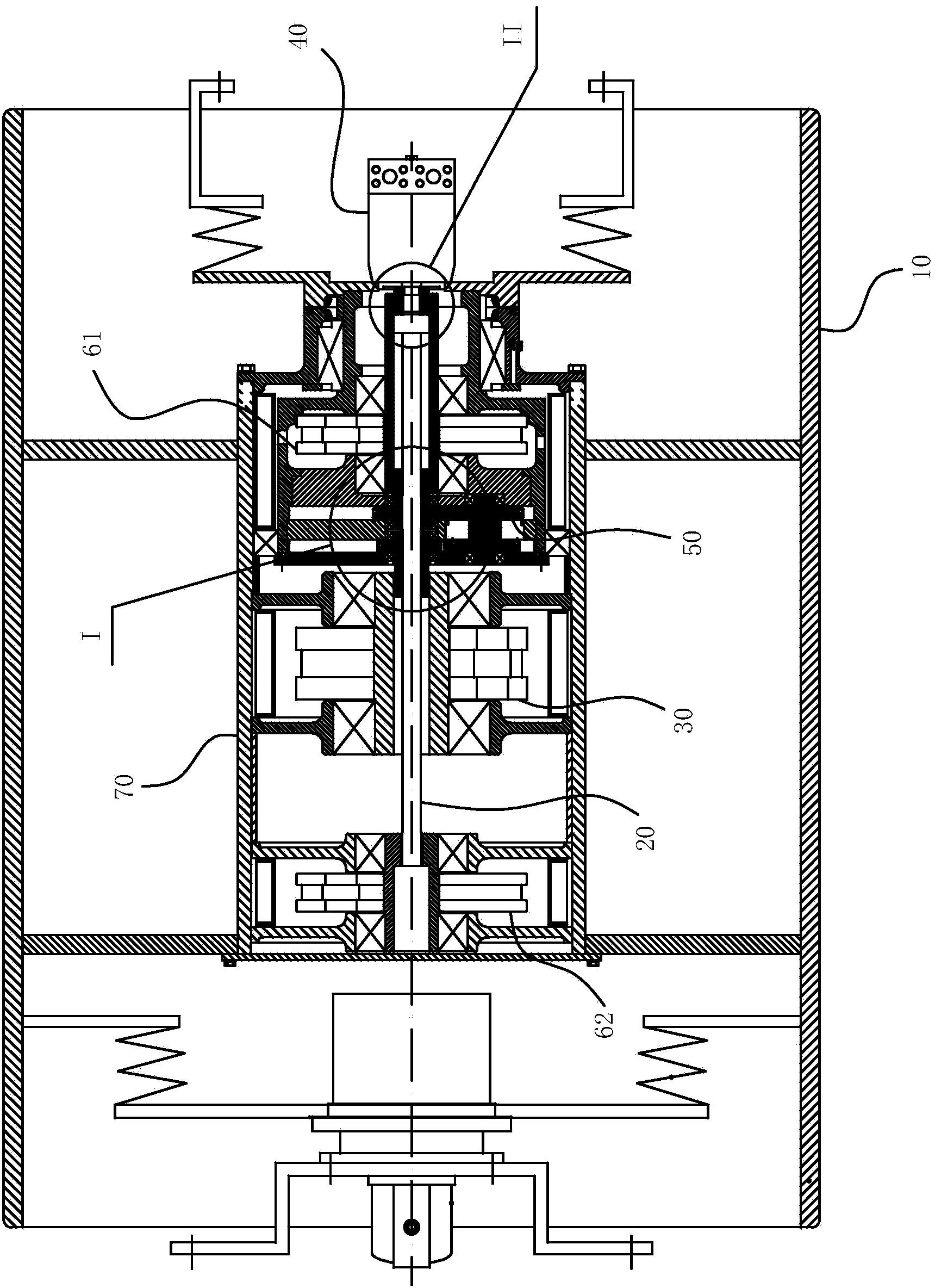
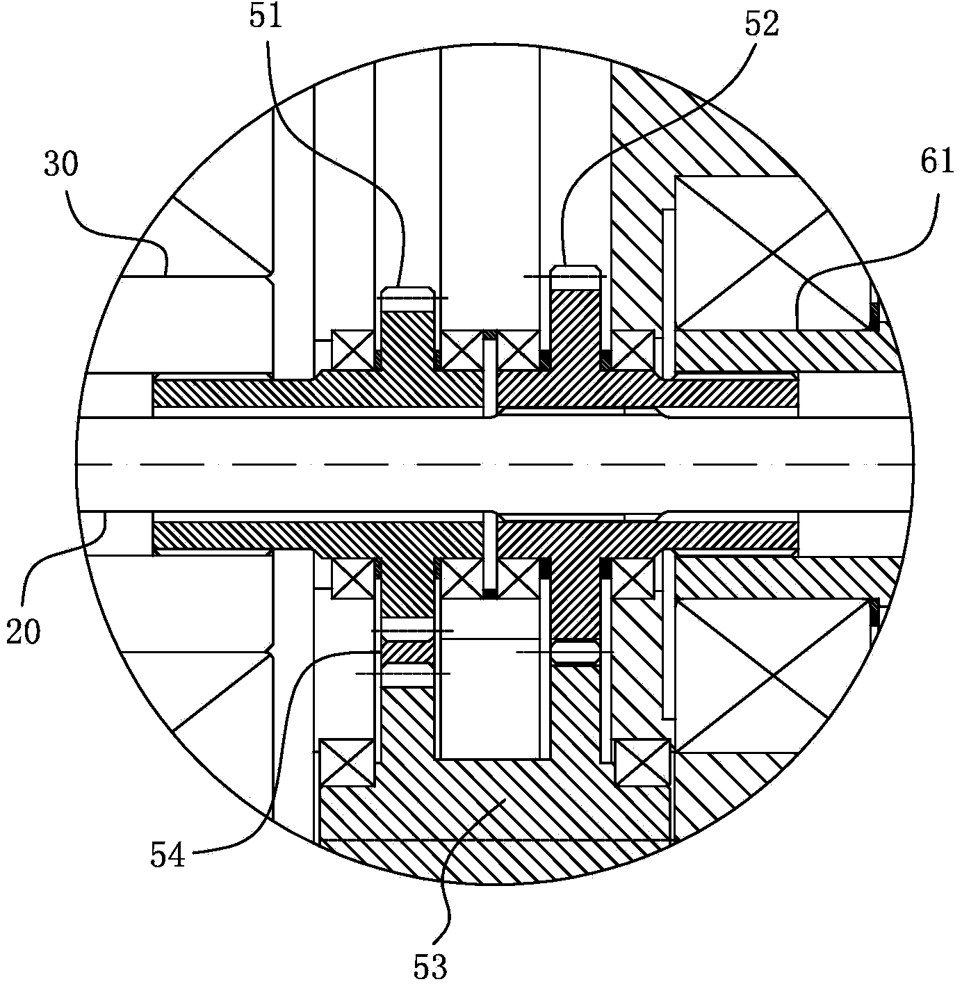
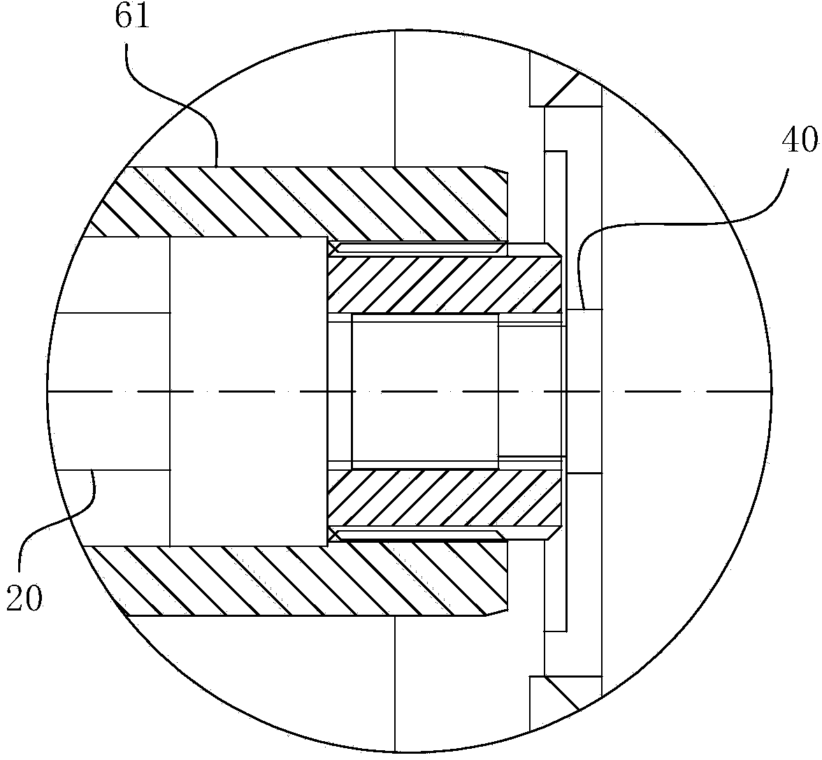
[0029] For ease of understanding, the attached Figure 1-3 Concrete structure and workflow of the present invention are described as follows:

[0030] Concrete structure of the present invention, can refer to figure 1As shown, it specifically includes a vibrating wheel 10 as an external steel wheel. The vibrating wheel has a built-in cylinder 70. The rotating shaft 20 is supported and fixed with a bearing in the cylindrical body 70. An external power source 40 (that is, a vibrating motor) is arranged on one side of the rotating shaft 20. ). The rotating shaft 20 is arranged in sequence from the end where the external power source 40 is located to the other end of the first forward rotation eccentric block group 61, the direction changing gear set 50, the reverse rotation eccentric block group 30 and the second forward rotation eccentric block group 62; A positive rotation eccentric block group 61 and a reverse rotation eccentric block group 30 are both sleeved on the rotatin...


PUM


Abstract

The invention belongs to the field of road roller equipment and particularly relates to an oriented vibrating wheel system of a driving gear box structure of a road roller. The oriented vibrating wheel system comprises a vibrating wheel, a rotating shaft, a forward eccentric block group and a reverse eccentric block group with the rotating direction opposite to that of the forward eccentric block group, wherein a direction-variable gear set is used for connecting the forward eccentric block group and the reverse eccentric block group, and changing the directions of the forward eccentric block group and the reverse eccentric block group and transferring power between the forward eccentric block group and the reverse eccentric block group; key joint fit with radial activity allowance is adopted between a power output shaft of the direction-variable gear set and a power output shaft of the forward eccentric block group, or between the power output shaft of the direction-variable gear set and a power input shaft of the reverse eccentric block group, or between the power output shaft of the direction-variable gear set and the power output shaft of the forward eccentric block group as well as the power output shaft of the direction-variable gear set and the power input shaft of the reverse eccentric block group. By using the oriented vibrating wheel system, the whole operating life of an inner gear can be effectively prolonged; in addition, influences of motion asynchrony, instant transmission impact and the like caused by small machining and assembling coaxiality errors of all parts and clearances among a plurality of layers of bearings are made up through one or more-layer key joint transmission.

Description

technical field [0001] The invention belongs to the field of road roller equipment, and in particular relates to a directional vibrating wheel system of a road roller transmission gear box structure. Background technique [0002] Vibratory rollers are machines that use their own gravity and vibration to compact various building and road construction materials; in highway construction, vibratory rollers are most suitable for compacting various non-cohesive soils, gravel, gravel mixtures and various widely used in asphalt concrete. The structures of the current directional vibratory rollers all include a cylinder and a vibrating shaft fixed therein. The cylinder is supported by bearings to be fixed on the vibrating wheel. The inner chamber of the cylinder is arranged in sequence along the axis of the vibrating shaft with a plurality of independent shaft parts and shafts. The eccentric block group of the bearing, so as to realize the directional excitation effect of the vibrat...

Claims


Application Information

Patent Timeline
IPC IPC(8): E01C19/28
Inventor 宋皓崔文平程国强
Owner 合肥永安绿地工程机械有限公司
Why Eureka
Try Eureka