Display device

Inactive Publication Date: 2006-07-27
SANYO ELECTRIC CO LTD
View PDF6 Cites 52 Cited by
  • Summary
  • Abstract
  • Description
  • Claims
  • Application Information

AI Technical Summary

Problems solved by technology

This causes a problem that, for example, in the open air, where ambient light intensity is high, contrast of the display area is reduced, and the display area is difficult t

Method used


Image

  • Display device
  • Display device
  • Display device

Examples


first embodiment

[0047] FIGS. 1 to 9C are views explaining the present invention and explain a case of adjusting luminance of a display area in a display data correction circuit.

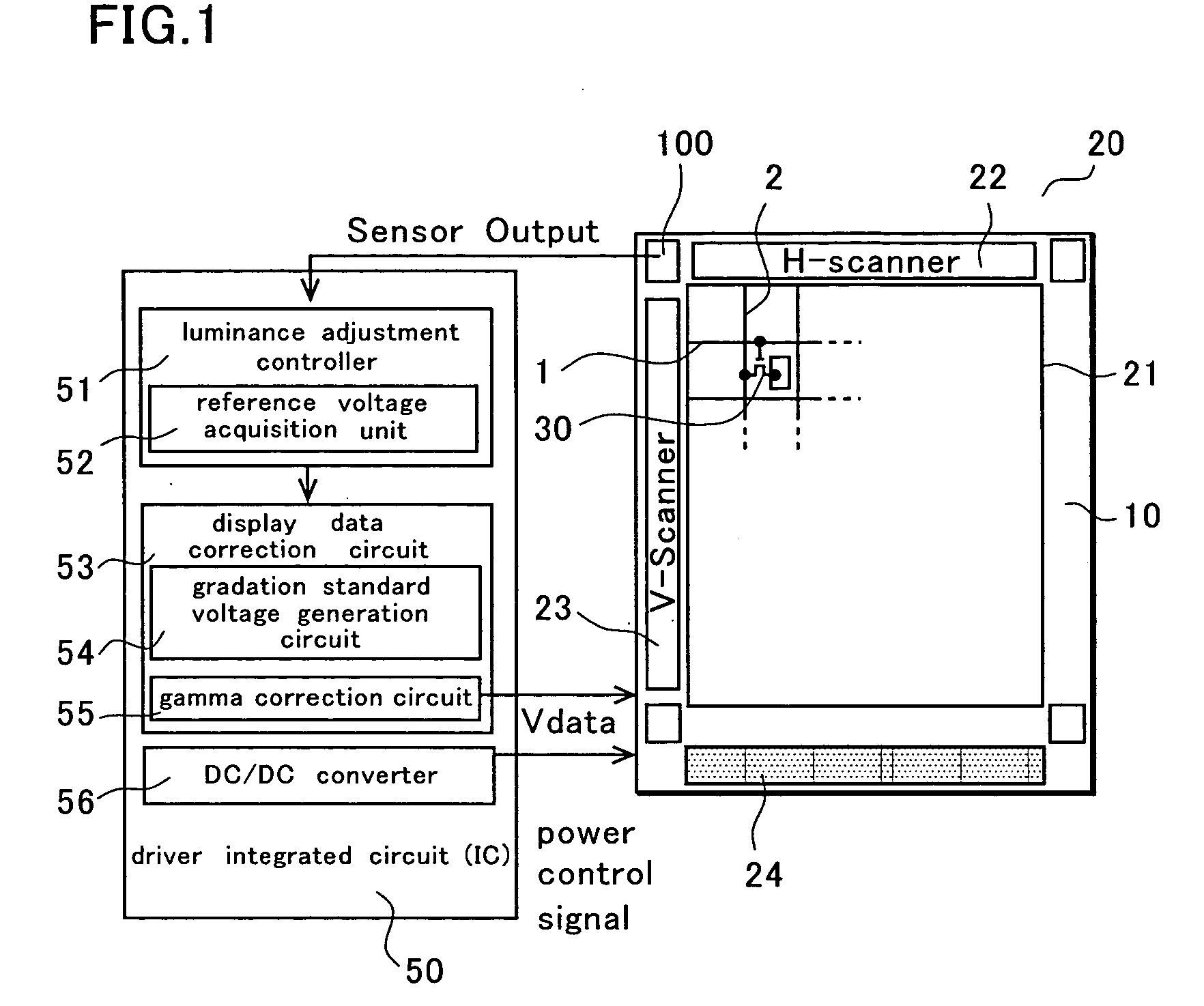
[0048]FIG. 1 is a schematic view showing a configuration of a display device.

[0049] A display device 20 includes a display area 21, a photo sensor 100, and a driver integrated circuit (IC) 50.

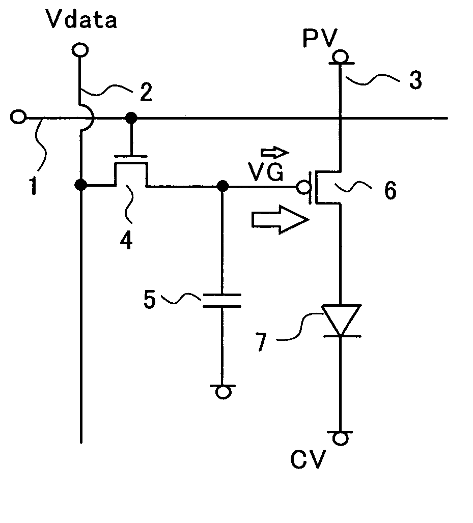
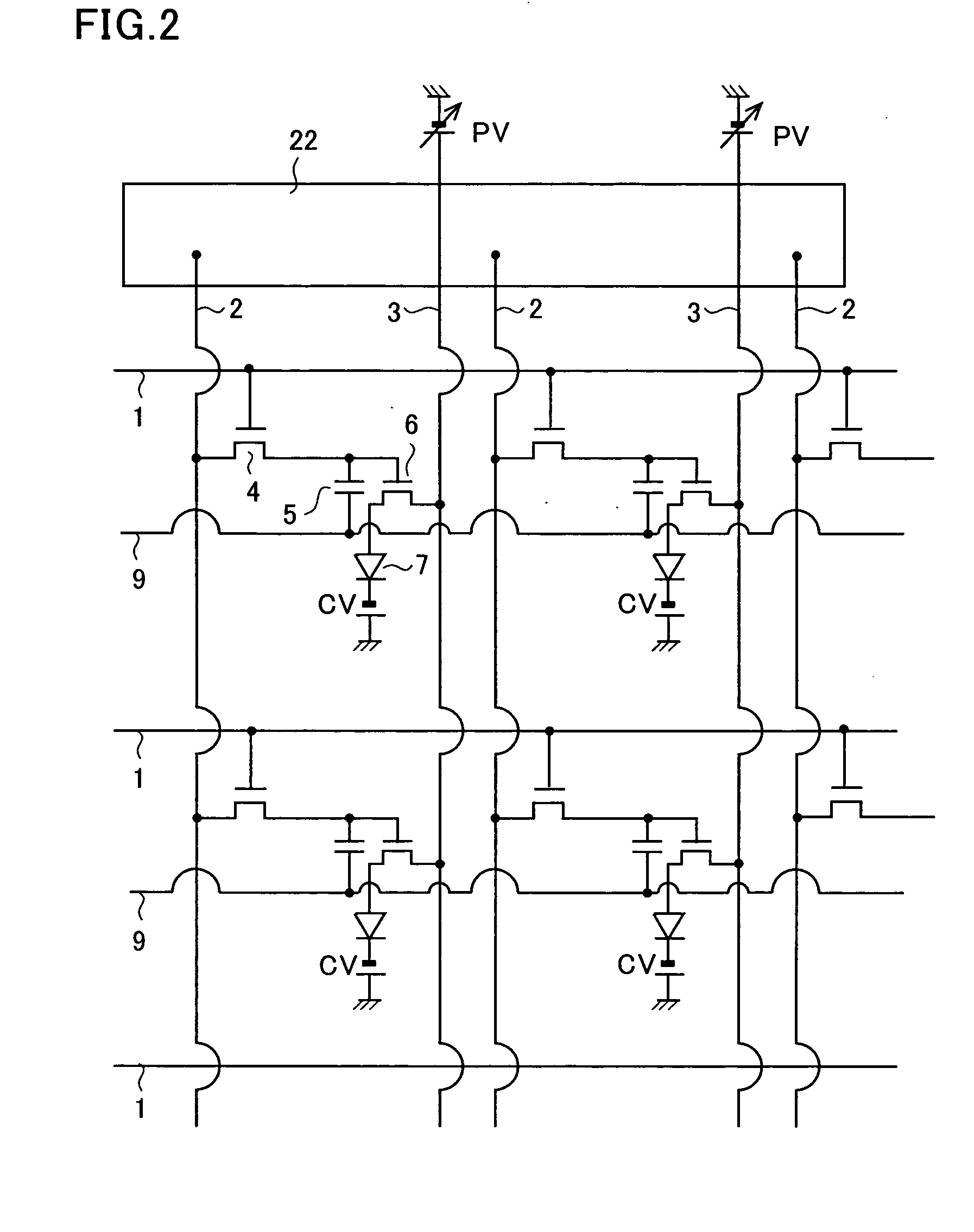
[0050] The display area 21 is formed of a plurality of display pixels 30 arranged in a matrix on an insulating substrate 10 of glass or the like. Each of the display pixels 30 includes an EL element having a light emitting layer between an anode and a cathode, a driving transistor to drive the EL element, and a selection transistor. Both of the driving and selection transistors are thin film transistors (hereinafter, referred to as TFTs).

[0051] On the substrate 10, a plurality of drain lines 2 and a plurality of gate lines 1 are arranged, and the display pixels 30 are arranged corresponding to individual intersections of the drain li...

second embodiment

[0128] The luminance adjustment controller 51 of the second embodiment includes a CV value calculation unit 57 and outputs a correction value to maintain constant contrast of the display area 21 according to ambient light intensity sensed by the photo sensor 100.

[0129] The luminance adjustment controller 51 includes a voltage changing circuit 58 within the DC / DC converter 56, which supplies a power source voltage of the driving TFTs driving the organic EL elements. The correction value outputted from the luminance adjustment controller 51 is inputted into the voltage changing circuit 58, and the power source voltage applied to the driving TFTs is changed to adjust the contrast of the display area 21.

[0130] The display data correction circuit 53 performs digital / analog (D / A) conversion of the data signals, and analog RGB data signals generated using the plurality of gradation display voltages are corrected in a gamma correction circuit 55. The data signals Vdata are outputted to dra...


PUM


Abstract

A photo sensor is disposed on the same substrate as that of a display area. External light sensed by the photo sensor is inputted into a luminance adjustment controller, and luminance necessary to maintain constant contrast is obtained. A correction value corresponding to the luminance to be adjusted is outputted as a white reference voltage or a value of a CV power source to be fed back to the display area. Constant contrast of the display area can be maintained even when surrounding light intensity varies. Moreover, an amount of electric current is adjusted according to the ambient light, leading to reduction in power consumption and extension of operating life.

Description

BACKGROUND OF THE INVENTION [0001] 1. Field of the Invention [0002] The present invention relates to a display device, and particularly to a display device which maintains constancy of contrast by adjusting luminance according to ambient light. [0003] 2. Description of the Related Art [0004] A recent display device, which is represented by a liquid crystal display (LCD) or an organic EL display using an organic EL element, has been increasingly reduced in size and thickness, and extended in life. [0005] The organic EL element, in particular, is self-luminous and does not require a backlight necessary for the liquid crystal display. Accordingly, the organic EL element is optimal for reducing the thickness of the display device. Moreover, the organic EL element does not limit viewing angles. The organic EL display is therefore highly expected to be put into practical use as a next-generation display device. [0006] By the way, the methods of driving the organic EL display is of two typ...

Claims


Application Information

Patent Timeline
IPC IPC(8): G09G5/00H05B44/00
CPCG09G3/3233G09G3/3291G09G2300/0842G09G2300/0866G09G2320/0271G09G2320/043G09G2320/0626G09G2320/066G09G2320/0673G09G2330/028G09G2360/144G09G3/30H05B33/26
Inventor NISHIKAWA, RYUJIOGAWA, TAKASHI
Owner SANYO ELECTRIC CO LTD
Why Eureka
Try Eureka