Therefore it becomes impossible to achieve a matching or
adaptation of the outer jacket to the form of the inner jacket.
As a result, it becomes necessary to manufacture the two jackets with a very high degree of matching shape accuracy, which necessitates the use of very complicated and costly production processes in view of the complicated geometry that is involved.
A further
disadvantage is that it is possible for hollow spaces or gaps to remain between the two jackets after they are joined together, whereupon these hollow spaces or gaps can lead to deformations,
cracking and ultimately failure of the inner jacket during operation of the
combustion chamber and thrust nozzle.
However, the nozzle walls of such thrust nozzles are subjected to
high pressure forces and high temperatures.
As a result, bulging or bending deformations and overstrain conditions can arise in the thrust nozzle walls, which jeopardize the proper functioning of the thrust nozzle according to specifications.
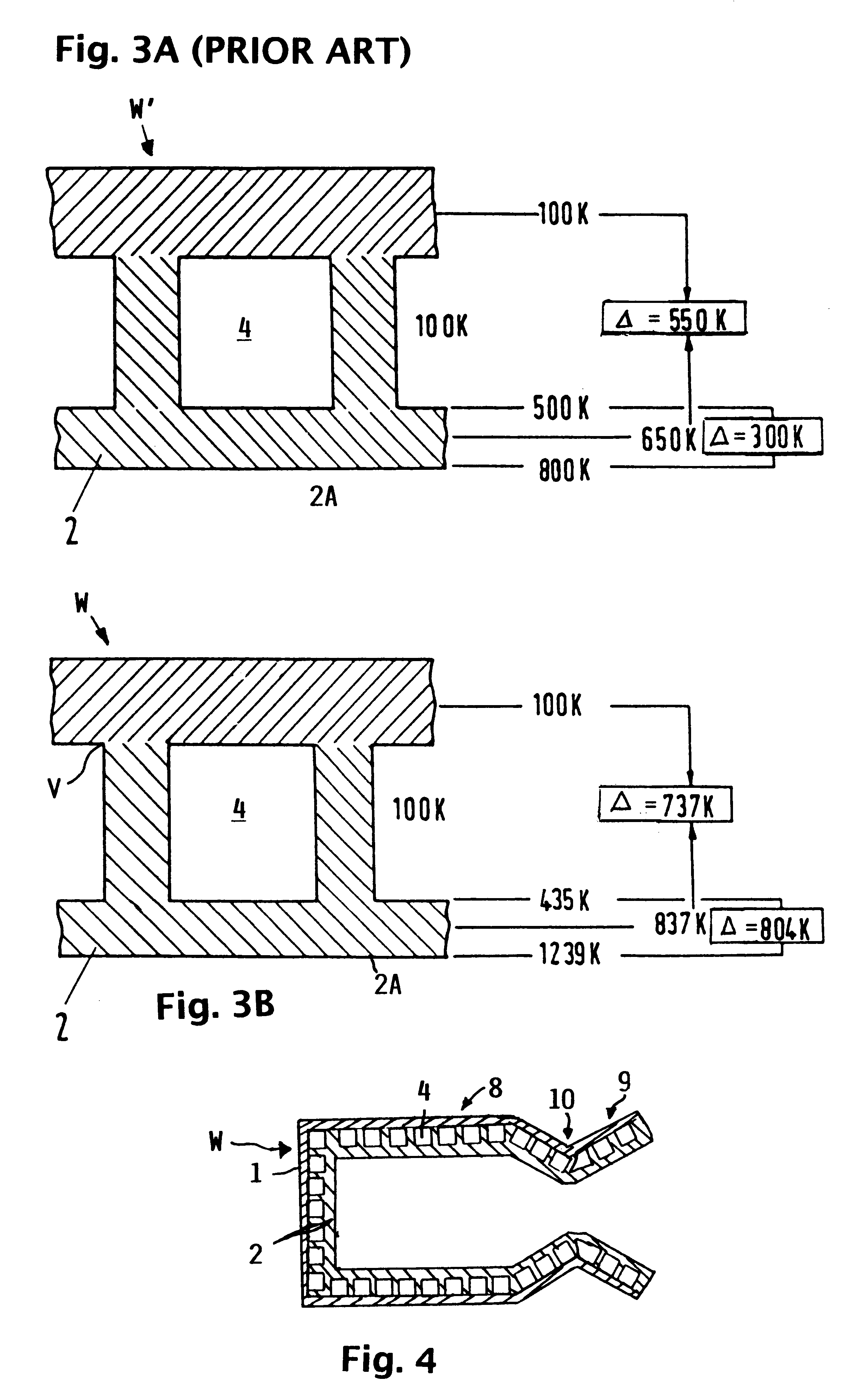
An additional difficulty arises in view of the so-called bi-
metal effect, due to the different
metal components of the inner jacket and of the outer jacket and due to the temperature differences through the multi-layered wall.
However, due to the required minimum strength in this context, an adequate straining distance is not available when the thrust nozzle is subjected to the extremely high thermal loading that is typical in the operation of high power engines.
Due to the high thermally induced tensions, which cause considerable plastic strain deformation of these holding elements particularly, the
operating life of the wall construction is drastically limited.
The above discussed limitation of the operating life is predominantly caused by a failure or defect formation, for example the formation of a crack in the
combustion chamber wall, after a limited number of load cycles and associated plastic deformations and creeping of the components due to the thermally limited strains, in other words due to the secondary stresses caused by the high thermally induced stresses amounting to approximately 80% of the total load.
For the above reasons, not only is the
reusability of the combustion chamber and thrust nozzle or overall engine
system sharply limited, but also the total costs of the booster or other propulsion
system are significantly increased.
Moreover, thrust losses and overloading of the various engine components, including the known turbo-pumps for pumping the fuel, oxidizer, and / or
coolant, also arise during operation of the engine, and, for example, lead to the formation of cracks or the like in these various components.
Even in the case if intermediate materials are arranged between the inner wall that is exposed to the hot gases and the outer supporting structure, such as sintered aluminum or foamed aluminum materials for example, which can take up and effectively absorb relatively high deformations, irreversible deformations in the plastic deformation range ultimately also arise, so that any such constructions are only suitable for
single use engine concepts.
However, the known materials for making such supporting elements do not comprise an adequate elastic strain characteristic.
As a result, the elastic strain required for the desired compensating effects during operation of the engine is not provided.

