
Tensile synchronous experiment device

A technique for synchronous experiments and tensile samples, applied in the field of experimental devices, can solve problems such as inability to test the tensile properties of materials, and achieve the effect of overcoming local temperature rise and avoiding direct contact heat transfer

Inactive Publication Date: 2012-12-19
NORTHWESTERN POLYTECHNICAL UNIV
View PDF9 Cites 18 Cited by
  • Summary
  • Abstract
  • Description
  • Claims
  • Application Information

AI Technical Summary

Problems solved by technology

[0005] In order to overcome the problem that the existing tensile test device cannot test the tensile properties of materials at high strain rates at high temperatures, the present invention provides a simultaneous tensile test device

Method used


Image

  • Tensile synchronous experiment device
  • Tensile synchronous experiment device
  • Tensile synchronous experiment device

Examples


Embodiment Construction

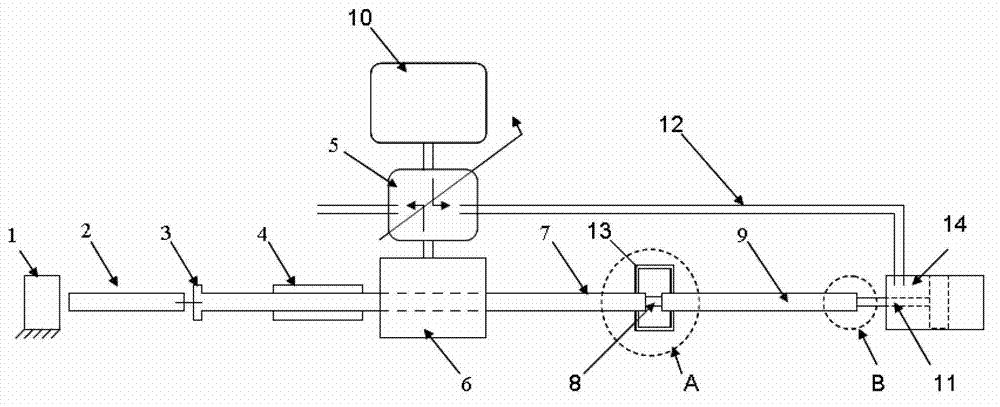
[0016] refer to Figure 3-6 , the stretching synchronous experiment device of the present invention comprises energy absorber 1, energy transmission rod 2, loading flange 3, impact tube 4, linkage launch valve group 5, impact gas chamber 6, incident rod 7, tensile sample 8, transmission Rod 9, synchronous air chamber 10, piston 11, gas pipe 12, high temperature furnace 13, stretching cylinder 14, thermocouple wire 15, heat insulating material 16. The energy absorber 1, the energy transmission rod 2, the impact gas chamber 6, the incident rod 7 and the transmission rod 9 are all placed on the platform. The energy transmission rod 2, the incident rod 7, and the transmission rod 9 are all cylindrical rods; the impact tube 4 is a tubular short rod, which is set on the incident rod 7 and can slide freely along the incident rod 7. The entire incident rod 7 penetrates the impact gas. Chamber 6; the collision position between the incident rod 7 and the impact tube 4 is designed as a ...


PUM


Abstract

The invention discloses a tensile synchronous experiment device for solving the technical problem that the conventional tensile experiment device cannot be used for testing tensile performance of a material at high temperature and high strain rate. The technical scheme is that an end head of tensile test piece is designed to be in the form of a convex edge, wherein an end head of a pull rod connected to the tensile test piece is designed to be in the form of a wedged groove; and high-temperature synchronization is realized under the control of a linkage emission valve block through matching of the two end heads. By designing a connection mode of the end head of the tensile test piece and the end head of the pull rod, a reserved gap is arranged; the tensile test piece and the pull rod are heat-insulated through a heat insulating material, so that direct contact heat transfer of the tensile test piece and the pull rod is avoided during heating of the test piece; and thus, an incidence bar and a transmission bar are kept in a normal temperature state in an experimental process all the time, and the problem of increase in local temperature of the incidence bar and the transmission bar in the background technology is solved.

Description

technical field [0001] The invention relates to an experimental device, in particular to a stretching synchronous experimental device. Background technique [0002] refer to figure 1 , figure 2 , literature "S.Nemat-Nasser, J.B.Isaacs, and J.E.Starrett, Hopkinson Techniques for Dynamic Recovery Experiments, Proc.R.Soc.(London) A[J], 435(1991) 371-391" and "S.Nemat- Nasser, Recovery Hopkinson Bar Techniques, Mechanical Test and Evaluation, Vol.8ASM Handbook, American Society for Metals, 2000, P.1068-1073" discloses a tensile test device for high strain rate tensile performance testing of materials. The device includes an energy absorber 1 , an energy transfer rod 2 , a loading flange 3 , an impingement tube 4 , an emission valve 5 , an impingement chamber 6 , an incident rod 7 , a tensile specimen 8 and a transmission rod 9 . Wherein the energy absorber 1, the energy transmission rod 2, the impact gas chamber 6, the incident rod 7 and the transmission rod 9 are all placed...

Claims


Application Information

Patent Timeline
IPC IPC(8): G01N3/18G01N3/02
Inventor 郭伟国朱泽曾志银邵小军
Owner NORTHWESTERN POLYTECHNICAL UNIV
Learn More