Visual card erasing device

A technology of visible card and erasing unit, which is applied in the direction of erasing devices, inking devices, and information-carrying cards, etc. It can solve the problems of affecting the ticketing speed and slowing down the printing speed, and achieve the goal of reducing operating costs and resource waste Effect

Active Publication Date: 2012-12-19
GUANGDONG RAILWAY TECH
View PDF7 Cites 2 Cited by
  • Summary
  • Abstract
  • Description
  • Claims
  • Application Information

AI Technical Summary

Problems solved by technology

The method of simultaneous erasing in the printer affects the speed of ticket sales, so setting an independent erasing device outside the printer to solve the problem of slow printing speed during continuous work has become a current research topic

Method used


Image

  • Visual card erasing device
  • Visual card erasing device
  • Visual card erasing device

Examples


Embodiment 1

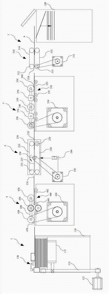
[0026] Such as Figure 1 to Figure 7 Schematically shows a visible card erasing device according to an embodiment of the present invention, which includes a card issuing module 1 , a cleaning unit 4 , a turning mechanism 2 , an erasing mechanism 3 and a card receiving module 5 arranged in sequence. The video card 6 to be erased is sent to the cleaning unit 4 through the card issuing module 1 for cleaning operation. After cleaning, the video card 6 is sent to the turning mechanism 2, and the turning mechanism 2 selectively After turning over, the video card 6 is sent into the erasing mechanism 3 . After the erasing mechanism 3 erases the information on the surface of the video card 6 , the video card 6 is finally sent into the card receiving module 5 .

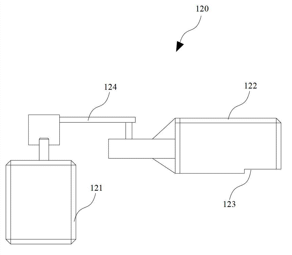
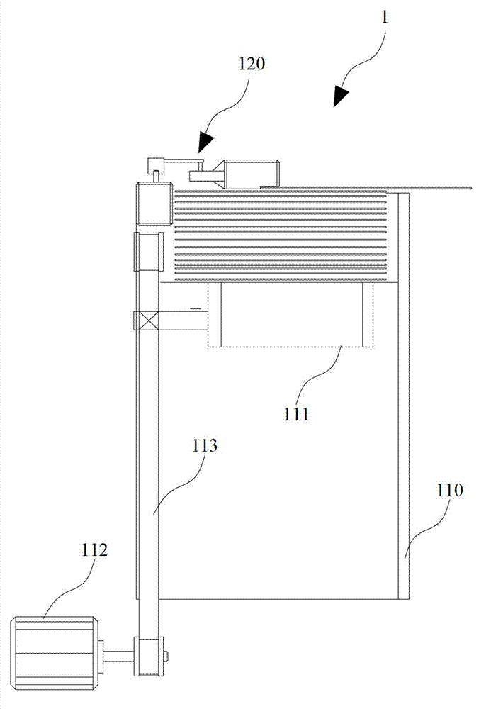
[0027] The card issuing module 1 includes a card box 110 containing the visible card 6 to be erased and a card pushing mechanism 120 located on the top of the card box 110 . The card pushing mechanism 120 includes a sixth mot...

Embodiment 2

[0035] Such as Figure 8 to Figure 9 Schematically shows a visible card erasing device according to yet another embodiment of the present invention, the difference from the first embodiment is that the thermal erasing unit in the second embodiment is a thermal erasing rod 380, and at the same time, the erasing The mechanism 3 also includes a fifth motor 390 , the thermal erasing rod 380 is driven to rotate by the fifth motor 390 , and the thermal erasing rod 380 is located above the first conveying mechanism 350 . The surface of the video card 6 is thermally erased by the rotating thermal erasing rod 380 to eliminate writing on the surface of the video card 6 . Moreover, through the cooperation of the rotating thermal erasing rod 380 and the first transmission mechanism 350, the transmission of the video card 6 can also be realized.

[0036] In addition to the fixed thermal erasing head and the rotating thermal erasing rod, the thermal erasing unit can also have other options...


PUM


Abstract

The invention discloses a visual card erasing device which comprises a card issuing module, an erasing mechanism and a card reclaiming module, wherein the card issuing module comprises a card box for containing visual cards to be erased and a card pushing mechanism at the top part of the card box; the card pushing mechanism is used for pushing the visual cards into the erasing mechanism; the erasing mechanism comprises a first motor, a first driving wheel, a first driven wheel, a first conveyer belt and a hot erasing unit; a first transmission mechanism is arranged below the hot erasing unit; a first channel through which the visual cards can pass is formed between the hot erasing unit and the first transmission mechanism; the card reclaiming module comprises a second transmission mechanism and a reclaiming box; the second transmission mechanism comprises a second motor, a second upper turning wheel group, a lower turning wheel group, a second upper conveyer belt and a second lower conveyer belt; a second channel through which the visual cards can pass is formed between the second upper conveyer belt and the second lower conveyer belt; and the reclaiming box is arranged at one side of a card outtake end of the second channel. With the adoption of the visual card erasing device, the erasing operation of the visual cards can be carried out effectively; and the visual card erasing device is independent from a printer.

Description

technical field [0001] The invention relates to ticket card recycling technology, in particular to a visible card erasing device. Background technique [0002] RFID cards that can be reprinted as visible cards. Common video card printers have an erasing function, but their erasing heads may cause scratches on the surface of the video card. In addition, this rub-and-print method also affects printing speed during continuous printing. [0003] Using visual cards as tickets or other tickets requires that the ticket information can be quickly printed in the ticketing system to ensure the speed of ticket sales. The way of erasing at the same time in the printer affects the ticketing speed, so setting an independent erasing device outside the printer to solve the problem of slow printing speed during continuous work has become a current research topic. Contents of the invention [0004] An object of the present invention is to provide a visual card erasing device that can per...

Claims


Application Information

Patent Timeline
Patent Type & Authority Applications(China)
IPC IPC(8): G07B3/00
CPCB41J2202/37B43L19/00B41J2/32B42D15/10G07B1/00G07B3/00B42D25/00
Inventor 付靖刘冬方
Owner GUANGDONG RAILWAY TECH
Why Eureka
Try Eureka