Energy storage on elevated platform and transfer method

A technology of energy transmission and energy storage devices, which is applied in the field of industrial lift trucks and can solve problems such as multiple packaging spaces

Active Publication Date: 2012-12-19
RAYMOND LTD
View PDF5 Cites 6 Cited by
  • Summary
  • Abstract
  • Description
  • Claims
  • Application Information

AI Technical Summary

Problems solved by technology

Routing wires on or inside a moving metal frame will necessarily require more packaging space

Method used


Image

  • Energy storage on elevated platform and transfer method
  • Energy storage on elevated platform and transfer method
  • Energy storage on elevated platform and transfer method

Examples


Embodiment Construction

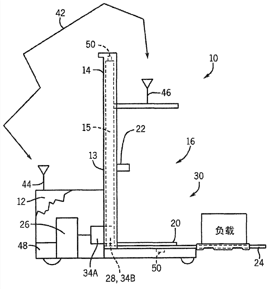
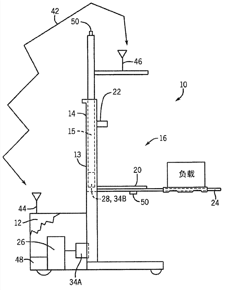
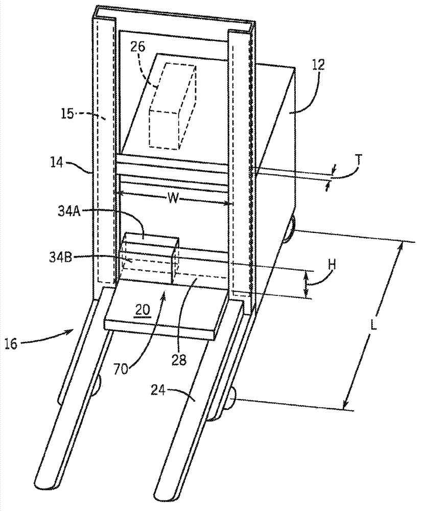
[0032] Referring now to the drawings, and more particularly to figure 1 and figure 2 , shows a representative general setup and arrangement of electrical circuits associated with a materials handling vehicle or forklift 10 according to an embodiment of the present invention. The forklift truck 10 includes a traction unit 12 , and a column 13 installed relative to the traction unit 12 and capable of vertical telescopic extension. The column 13 comprises a fixed base 14 and at least one telescopic column portion 15 to which a vertically movable platform 16 is connected. The telescoping column section 15 raises and lowers the platform 16 .

[0033]In one embodiment of a lift truck, the platform 16 includes an operator station or cab 18 and a platform fork 24 . The operator cab 18 includes an operator platform 20 on which an operator sits and / or stands, and an operator console 22 for operating the forklift 10 , including the functions of the operator platform 16 . The console...


PUM


Abstract

A lift truck includes a secondary rechargeable energy storage device on a vertically movable platform that is separate from a primary rechargeable energy storage device on the lift truck's main tractor unit. Wires or hoses for transfer of power or controls between the main tractor unit and the platform are reduced or eliminated. The quantity of energy stored in the secondary rechargeable energy storage device is sufficient to power platform electrical loads for a predetermined amount of time until the platform is lowered. When the platform is lowered, the secondary rechargeable energy storage device is recharged by the primary energy storage device.

Description

[0001] Cross references to related patent applications [0002] This patent application is filed on March 1, 2010, US Patent Application No. 12 / 714,977, and the title of the invention is "Energy Storage On An Elevated Platform And Transfer Method (Energy Storage On An Elevated Platform And Transfer Method)" Subsequent application, which is incorporated herein by reference. [0003] Statement on Federally Sponsored Research and Development [0004] Not applicable. technical field [0005] The invention relates to the field of industrial lift trucks, in particular to an energy storage and transmission system and method on a lift truck platform. Background technique [0006] Forklifts are designed in a variety of configurations to perform a variety of tasks. Most tasks include operating a vertically movable platform to raise and lower operators and / or loads. The energy used to operate the forklift, including power for the traction unit and power for lifting and / or operating...

Claims


Application Information

Patent Timeline
Patent Type & Authority Applications(China)
IPC IPC(8): H02J7/34H02J15/00B60L50/30
CPCY02T10/7027Y02T10/7022Y02T10/7216Y02T10/70
Inventor P·P·麦克卡比D·G·拉德勒尔
Owner RAYMOND LTD
Why Eureka
Try Eureka