Plasma treatment apparatus

A processing device and plasma technology, applied in the directions of plasma, gaseous chemical plating, coating, etc., can solve the problems of poor substrate processing uniformity, poor plasma density distribution uniformity, and film quality degradation, etc., and achieve uniformity. The effect of improving the uniformity of film thickness distribution

Inactive Publication Date: 2012-12-19
NISSIN ELECTRIC CO LTD
View PDF6 Cites 5 Cited by
  • Summary
  • Abstract
  • Description
  • Claims
  • Application Information

AI Technical Summary

Problems solved by technology

[0004] For example, the capacitively coupled plasma processing apparatus has the following problems: when a high voltage is applied to the plasma, the potential of the plasma rises, and charged particles (such as ions) in the plasma are injected into the substrate with high energy and Collision with the substrate increases the damage to the film formed on the substrate and reduces the film quality
As a result, for example, there is a problem that, since charged particles (for example, ions) in the plasma are injected into the substrate with high energy and collide with the substrate, the damage to the film formed on the substrate becomes larger and the film quality deteriorates.
As a result, the uniformity of the plasma density distribution in the length direction of the antenna is deteriorated, and thus the uniformity of the substrate processing is deteriorated

Method used


Image

  • Plasma treatment apparatus
  • Plasma treatment apparatus
  • Plasma treatment apparatus

Examples


Embodiment Construction

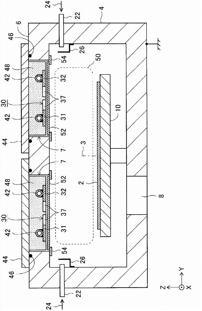
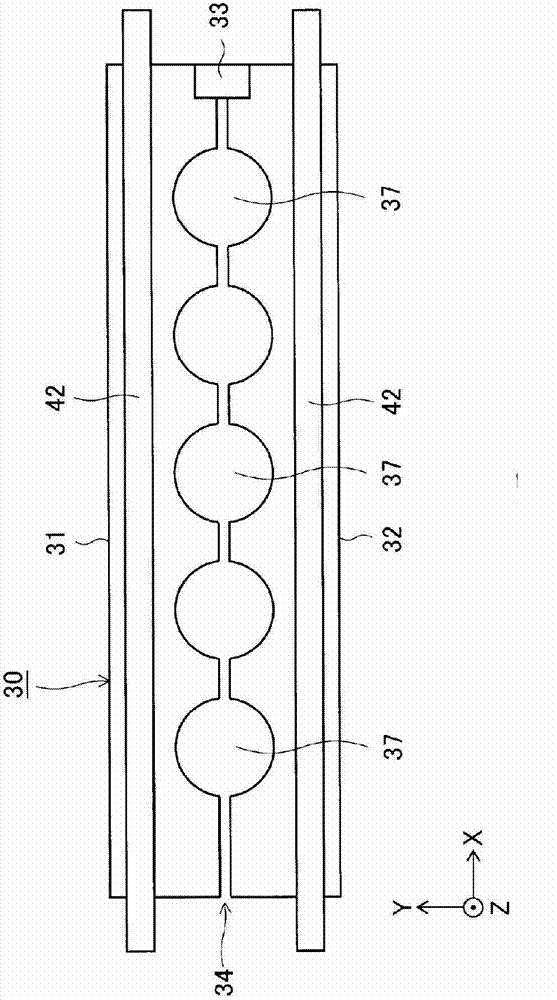
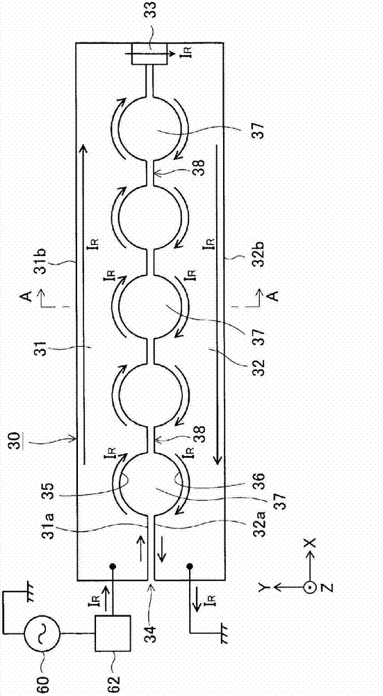
[0097] figure 1 One embodiment of the plasma processing apparatus of the present invention is shown, and one antenna 30 of the plasma processing apparatus is separated and shown in Figure 2 ~ Figure 4 . exist figure 1 , figure 2 In other figures, cooling pipes are omitted for simplification of illustration. The same applies to other embodiments described later.

[0098] In order to show the orientation of the antenna 30 and the like, the X direction, the Y direction, and the Z direction that are perpendicular to each other at one point are marked in each figure. The Z direction is a direction parallel to the vertical line 3 erected on the surface of the substrate 2, and the Y direction is a direction perpendicular to the vertical line 3. In order to simplify the expression, the directions are respectively referred to as the up-down direction Z and the left-right direction Y. . The X direction is a direction perpendicular to the vertical line 3 and is the longitudinal d...


PUM


Abstract

The invention provides a plasma treatment apparatus which can reduce an effective inductance of an antenna and restrain a potential difference generated between two ends in a length direction of the antenna to be a small potential difference, thereby restraining a plasma potential to be a low potential and raising uniformity of plasma density distribution in the length direction of the antenna. The antenna (30) which constitutes the plasma treatment apparatus and has a substantially-straight flat shape presents a return conductor structure, i.e., two rectangular conductor plates (31, 32) are disposed in a manner that the two plates are in the same plane, close to and parallel with each other, and provided with a gap (34) therebetween, and one end in the length direction (X) of the two conductor plates are connected by using a conductor (33). High-frequency currents (1R) flow to the two conductor plates (31, 32) in a reverse manner. Opening parts (37) form on an edge at the gap side of the two conductor plates (31, 32) and are dispersedly disposed in the length direction (X) of the antenna (30).

Description

technical field [0001] The present invention relates to a plasma processing apparatus for performing, for example, film formation, etching, and ashing on a substrate by a plasma chemical vapor deposition (CVD) method using plasma. , sputtering (sputtering), etc., and more specifically, the present invention relates to an inductively coupled plasma processing apparatus that uses an induced electric field to generate plasma and uses the plasma to process a substrate , the induced electric field is generated by flowing a high-frequency current into an antenna. Background technique [0002] As a device belonging to a plasma processing device that generates plasma using high frequency, there are capacitively coupled plasma processing devices that generate capacitively coupled plasma (abbreviated as CCP), and inductively coupled plasma processing devices that generate inductively coupled plasma (abbreviated as ICP). Plasma treatment device. [0003] In simple terms, the capaciti...

Claims


Application Information

Patent Timeline
Patent Type & Authority Applications(China)
IPC IPC(8): H05H1/46
CPCH01J37/3211C23C16/402C23C16/507H05H1/46H01L21/3065
Inventor 安东靖典
Owner NISSIN ELECTRIC CO LTD
Why Eureka
Try Eureka