Female terminal

A female terminal and terminal technology, applied in the field of female terminals, can solve the problems of higher insertion force and increased sliding resistance, and achieve the effect of preventing the increase of insertion force, preventing the increase of insertion force and reliable electrical conductivity.

Active Publication Date: 2012-12-19
FURUKAWA ELECTRIC CO LTD +1
View PDF6 Cites 14 Cited by
  • Summary
  • Abstract
  • Description
  • Claims
  • Application Information

AI Technical Summary

Problems solved by technology

In this way, there is a problem that when the convex portion is further slid at a position where the other convex portion has slid, the sliding resistance of the convex portion inserted into the lead plate increases, and therefore, the insertion force becomes high.

Method used


Image

  • Female terminal
  • Female terminal
  • Female terminal

Examples


Embodiment Construction

[0071] One embodiment of the present invention will be described below based on the drawings.

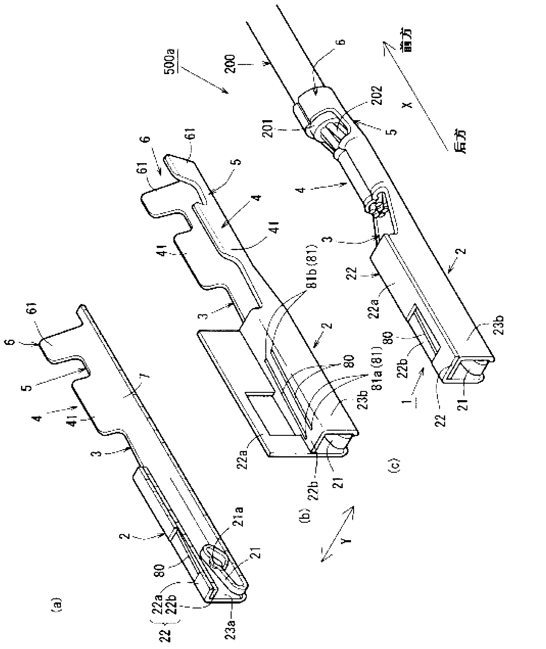
[0072] in addition, figure 1 and figure 2 This is an explanatory diagram showing the male crimp terminal 1. here, figure 1 (a) in (a) shows a cross-sectional perspective view of the female crimp terminal 1 divided in the center of the width direction Y, figure 1 (b) is a perspective view showing the female crimp terminal 1 in the middle of assembly, figure 1 (c) is a perspective view of the female crimping terminal 1 in a state where the covered electric wire 200 is crimped to the core wire crimping portion 4 .

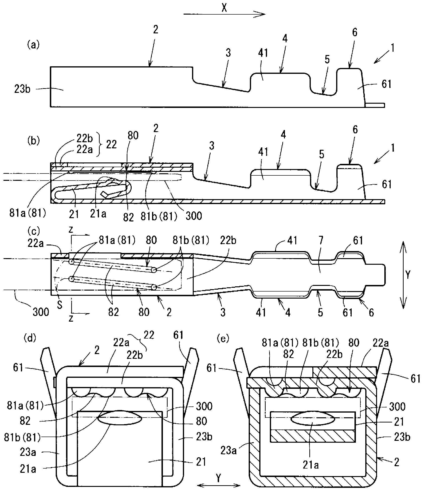
[0073] also, figure 2 (a) in the figure shows the side view of the female crimp terminal 1, figure 2 (b) is a cross-sectional view of the female crimp terminal 1 at the central position in the width direction Y, figure 2 (c) in means figure 1 (b) is a plan view of the female crimp terminal 1 before assembly. and, figure 2 (d) in represents the front view of t...


PUM


Abstract

Disclosed is a female terminal that can reliably conduct electricity while suppressing an increase in the insertion force on the fitting means of an insertion tab on a male terminal. The female crimp terminal (1) is equipped with a box (2) that permits the insertion of the insertion tab (300) on the male terminal, wherein the box (2) is equipped with an elastic contact piece (21) that elastically comes into contact with the inserted insertion tab (300) and an inner roof section (22b) that faces the elastic contact piece (21) and fits the inserted insertion tab (300) by sandwiching the tab with the elastic contact piece (21), semispherical projections (81) that project toward the elastic contact piece (21) are formed on the inner roof section (22b), front semispherical projections (81b) are disposed relative to rear semispherical projections (81a); in positions intersecting the insertion direction (X) of the insertion tab (300), and diagonal beads (80) having semispherical projections (81) formed on both ends thereof are disposed in the surface of the inner roof section (22b) in a manner intersecting with the width direction (Y).

Description

technical field [0001] The present invention relates to a female terminal mounted on a connector or the like, which is used, for example, for connection of a wiring harness for a vehicle. Background technique [0002] Conventionally, many wire harnesses are arranged in a vehicle, and these wire harnesses are connected by connectors. Such a connector incorporates a crimping terminal that is crimped and fixed corresponding to each of the covered electric wires constituting the wire harness. [0003] Such a crimping terminal is constituted by a pair of a male terminal provided with a flat plate-shaped insertion lead plate and a female terminal provided with a box portion allowing the insertion lead plate to be inserted as shown. The terminals are mounted inside the connector in a state of being connected to the covered electric wires, respectively. [0004] In addition, the box part of the female terminal has the following structure: the elastic contact part in elastic contac...

Claims


Application Information

Patent Timeline
Patent Type & Authority Applications(China)
IPC IPC(8): H01R13/11H01R13/115
CPCH01R13/187H01R13/113
Inventor 吉田和生川村幸大
Owner FURUKAWA ELECTRIC CO LTD
Why Eureka
Try Eureka