Coupler

A coupling, a pair of technology, applied in the direction of electrical components, electromechanical devices, electromechanical transmission devices, etc., can solve the problems of click winding burnt, disciplinary clothing, leakage, etc., to achieve non-contact, prolong service life, and practical functions Effect

Inactive Publication Date: 2012-12-26
李凡
View PDF0 Cites 0 Cited by
  • Summary
  • Abstract
  • Description
  • Claims
  • Application Information

AI Technical Summary

Problems solved by technology

[0002] At present, in the technical mechanical design and manufacturing industry, the method of extending the shaft or contact mechanical coupling is usually used to solve the problem that the power machine drives the driven wheel, but the sealing ring must be used to prevent leakage under the condition of liquid, and the sealing ring has been tested for a long time. After wear and tear, it is easy to cause leakage, which will cause the click winding to burn out and discipline clothing, resulting in a lot of losses

Method used


Image

  • Coupler

Examples


Embodiment Construction

[0009] In order to deepen the understanding of the present invention, the present invention will be further described below in conjunction with the embodiments and accompanying drawings. The embodiments are only used to explain the present invention and do not constitute a limitation to the protection scope of the present invention.

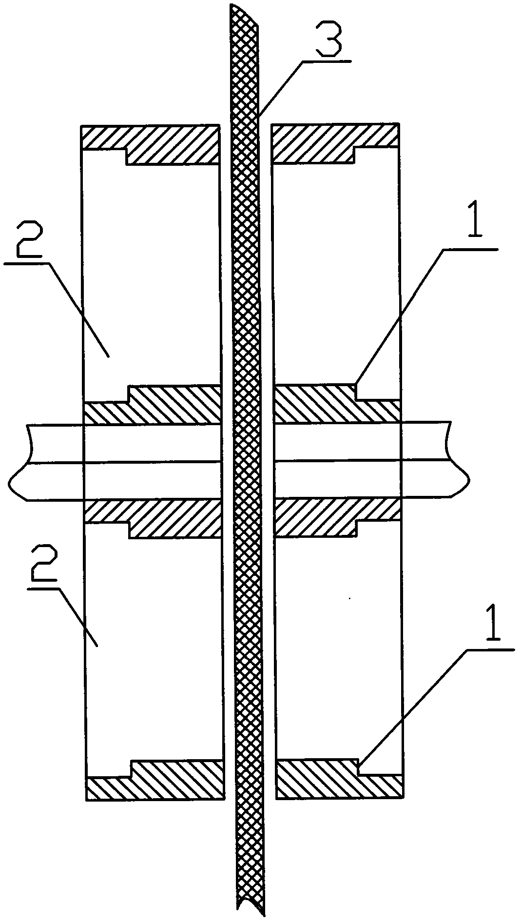
[0010] Such as figure 1 It shows a coupling of the present invention, including a pair of turntables 1, the turntables 1 are installed symmetrically up and down, and a balance magnet 2 is provided inside each turntable 1, and the balance magnets 2 are symmetrically arranged, and in the middle of the turntable 1 There is a magnetic medium casing 3 running through it, and the magnetic medium casing 3 can transmit power to any turntable 1. According to the law that the SN poles of the balance magnet 2 attract each other, the other turntable 1 will rotate accordingly, forming a non-contact of couplings.


PUM


Abstract

The invention discloses a coupler, which comprises a pair of rotary trays which are symmetrically arranged in the vertical direction; a balancing magnetic steel is arranged in each of the rotary trays, and the balancing magnetic steels are symmetrically arranged; magnetic medium shells are arranged in the middle parts of the rotary trays in a penetrating way; the magnetic medium shells are capable of transmitting the power to any one of the rotary trays, and, depending on the rule that opposites attract of the south (S) and north (N) poles of the balancing magnetic steels, the other rotary tray can rotate as well, thereby forming a contact-free coupling. The coupler is compactly and skillfully structured and is practical in function; the contact free of the coupling is realized, and the service life of the coupling is prolonged.

Description

Technical field: [0001] The invention relates to a shaft coupling. Background technique: [0002] At present, in the technical mechanical design and manufacturing industry, the method of extending the shaft or contact mechanical coupling is usually used to solve the problem that the power machine drives the driven wheel, but the sealing ring must be used to prevent leakage under the condition of liquid, and the sealing ring has been tested for a long time. After wear and tear, it is easy to cause leakage, which will cause the click winding to be burned and discipline inspection clothing, resulting in a lot of losses. Invention content: [0003] The object of the present invention is to overcome the above disadvantages and provide a magnetic field non-contact shaft coupling with compact structure, ingenious, practical functions, and capable of solving liquid leakage well. [0004] The purpose of the present invention is achieved through the following technical solutions: a...

Claims


Application Information

Patent Timeline
Patent Type & Authority Applications(China)
IPC IPC(8): H02K51/00
Inventor 李凡
Owner 李凡
Why Eureka
Try Eureka