Control of loudspeaker output

A loudspeaker, controlled technology applied in the direction of amplification control, gain control, combination of control types, etc.

Active Publication Date: 2012-12-26
GOODIX TECH HK CO LTD
View PDF3 Cites 23 Cited by
  • Summary
  • Abstract
  • Description
  • Claims
  • Application Information

AI Technical Summary

Problems solved by technology

Furthermore, the complete signal (or, frequency band in the case of the multi-band approach) is affected by the gain control, and even the lower amplitude bands that do not cause heating of the voice coil are also affected by the gain control

Method used


Image

  • Control of loudspeaker output
  • Control of loudspeaker output
  • Control of loudspeaker output

Examples


Embodiment Construction

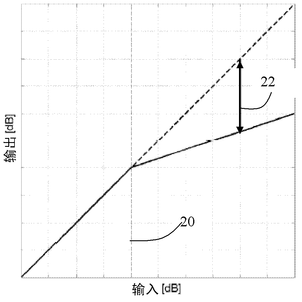
[0040] The present invention provides a loudspeaker drive circuit in which a dynamic range compressor implements a non-linear gain function between an input signal to the dynamic range compressor and an output signal from the dynamic range compressor. The output is used to drive the loudspeaker, and the operating parameters of the dynamic range compressor are varied according to the feedback criteria.

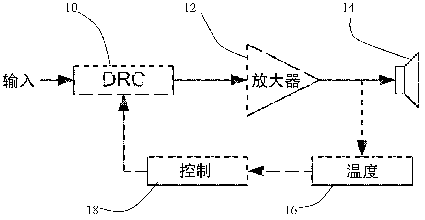
[0041] figure 1 A basic implementation of the proposed invention is shown. As an example, the description uses voice coil temperature, but this could also be a measure of power consumption or acoustic distortion.

[0042]A dynamic range compression (DRC) module 10 processes the input signal, and the output of the dynamic range compression (DRC) module 10 is amplified by an amplifier 12 and sent to a speaker 14 . The amplifier implements the function of the speaker driver. The temperature estimation unit 16 estimates the temperature of the loudspeaker voice coil, eg from the ...


PUM


Abstract

A loudspeaker drive circuit uses a dynamic range compressor to implement a non-linear gain function between the input signal to the dynamic range compressor and an output signal from the dynamic range compressor. The output is used to drive a loudspeaker, and the operating parameters of the dynamic range compressor are varied in dependence on a criterion, such as the estimated voice coil temperature, the power consumption or the acoustical distortion.

Description

technical field [0001] The present invention relates to the control of loudspeaker output. Background technique [0002] Loudspeakers are devices used to convert electrical energy into sound energy. [0003] However, most of the electrical energy applied to a loudspeaker will result in heat dissipation, which causes many common loudspeaker deficiencies. In order to prevent thermal damage (permanent or temporary), it is desirable to measure the voice coil temperature of the loudspeaker and adjust the input so that the temperature is not greater than a certain limit. [0004] One method for estimating the voice coil temperature is to use a mathematical model of the loudspeaker that uses a number of estimated parameters, see for example Audio Eng .Soc.52, 3-25, Klippel, W., 2004 "Nonlinear Modeling of the Heat Transfer in Loudspeakers". [0005] A different approach is to use the tone at the evaluation frequency, directly measure the current and voltage in the voice coil, an...

Claims


Application Information

Patent Timeline
Patent Type & Authority Applications(China)
IPC IPC(8): H04R3/00H03G7/08H03G3/20
CPCH03F3/181H04R3/007H03G7/002H03G9/025H04R29/003H03F1/52H03F2200/03H03F2200/447
Inventor 泰穆金·高塔马
Owner GOODIX TECH HK CO LTD
Why Eureka
Try Eureka