Falling-film stripper for carbamate decomposition

A technology of carbamate and stripper, applied in the direction of separation method, distillation separation, tube still, etc., can solve the problems such as unable to support the increased flow rate, and achieve the effect of effective quantity and size, and compact overall design

Inactive Publication Date: 2012-12-26
CASALE SA
View PDF5 Cites 2 Cited by
  • Summary
  • Abstract
  • Description
  • Claims
  • Application Information

AI Technical Summary

Problems solved by technology

Existing stripper could not support increased flow rate due to flooding issues

Method used


Image

  • Falling-film stripper for carbamate decomposition
  • Falling-film stripper for carbamate decomposition
  • Falling-film stripper for carbamate decomposition

Examples


Embodiment Construction

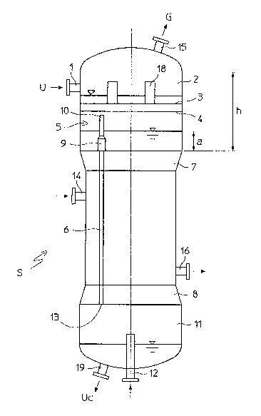
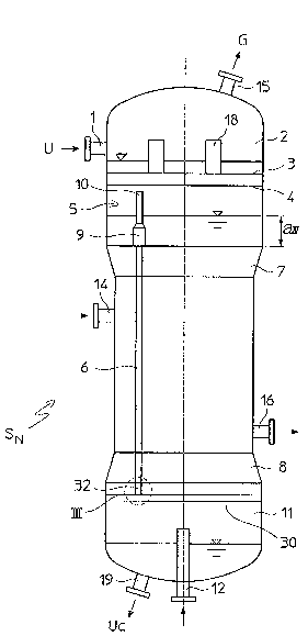
[0033] Such as figure 2 Shown is the stripper S of the present invention N . Those features that are common to the existing stripper diagram in Figure 1 are indicated by the same reference numerals and only new features are discussed here.

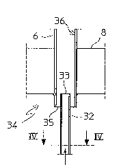
[0034] In the bottom liquid header box 11, the stripper S of the present invention N There is a perforated plate tray 30 with liquid drain holes 31 ( Figure 4) and carry a plurality of chimneys 32 . Each chimney 32 is a tube smaller than the main bundle tube 6 and has a bottom end connected to the tray 30 and a top portion 33 which enters the respective tube 6 and communicates with the chamber 11 , and above the bottom portion 34 of the tube 6 ( image 3 ).

[0035] according to Figure 5 In the embodiment, the gas riser 32 is supported by a tray 30a, and the tray 30a has no liquid drainage holes. The concentrated urea solution Uc gathers at the tray 30 a and overflows from the downcomer 37 .

[0036] At said bottom end portion 3...


PUM


Abstract

A stripper (S N ) for carbamate decomposition and ammonia plus carbon dioxide recovery from a urea solution (U) is realized with a shell-and-tube heat exchanger, where a liquid falling film of urea solution and a counter-current gaseous flow of a stripping medium fed to a bundle of surface-heated tubes (6); the stripping medium such as carbon dioxide is distributed into the tubes (6) by a plurality of gas risers (32); the gas risers are preferably associated to a perforated tray (30) in the bottom chamber (11) of the stripper. Revamping of a conventional CO 2 stripper is also disclosed.

Description

Technical field [0001] The present invention involves a diaphragm and carbon dioxide of ammonia and carbon dioxide from the outflow of ammonia and from the influx of the synthetic urea reactor.Specifically, the invention involves a gaseous steam -lifted medium such as carbon dioxide, which is distributed in the steam pipe. Background technique [0002] In the production process of urea, it is well known to supply the outflow of the reactor to the steam Tower. In the steam Tower, the amino -aminate is decomposed into ammonia and carbon dioxide with the function of heating and anti -extract. [0003] The diaphragm -type steam tower is basically a vertical tube shell heat exchanger, including the top tube box and the bottom pipe box, which uses the tube to flow through the tube.Provide the reactor out of the pipe box; supply the steam -lifted medium to the tube box in the lower part, and collect the concentrated urea solution from the tube.The gas phase including steam -lifted mediu...

Claims


Application Information

Patent Timeline
Patent Type & Authority Applications(China)
IPC IPC(8): B01D1/06B01D1/14B01D3/04C07C273/04B01D3/00
CPCC07C273/04B01D3/04B01D3/008B01D1/06B01D1/14Y10T29/49718Y02P20/141
Inventor 安德里亚·斯考托达米亚诺·维西奥提
Owner CASALE SA
Why Eureka
Try Eureka